Controlling Force—and Managing Expectations, Part 1
Force control is used in many applications where objects must be grabbed or formed into a shape. Measuring the exerted force can be done in two ways. The first is to use a load cell. Load cells can be very accurate with a quick response. The problem is, where should the load cell be mounted? If the load cell is mounted at the end of the piston rod, the cables leading to the load cell are easily damaged. It is also possible to mount the load cell on the cap end of the cylinder where the cables do not need to be in the work area.
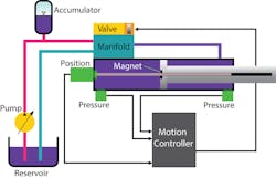
The problem is that if the cylinder is supported any place except at the end of the cylinder, those supports will absorb some of the load and the force readings will not be as accurate. The second way of measuring force is to mount pressure sensors to monitor the pressure on each side of the piston. The force can be calculated using the cap and rod pressures, multiplying by the corresponding areas, and subtracting to find the net force.
This calculation does not account for seal friction, so the true force value is actually slightly lower than calculated. This error is relatively small on big presses where the diameter of the cylinder is small relative to the area of the piston or rod. Applications with small diameter cylinders may have significant friction relative to the force being applied. In these applications load cells should be considered.
The optimal place to mount pressure sensors is where the flow is the slowest and where the pressure sensors will not trap air. If the cylinder is mounted horizontally, it is best to attach the pressure sensors to the bottom of the cylinder; this way the oil flow will be slow, and the pressure sensors will not trap air.
A common mistake is to mount the pressure sensors using a small plate between the valve and the cylinder. Although the pressure sensors will not trap air this way, they will be subject to turbulence that creates a noisy force reading signal. If the application only requires force control while there is little or no flow, this may be fine.
Both load cells and pressure sensors should have a fast response time because pressure/force transients can be very fast. Pressure sensors, load cells, and electrons should have a response time of at least 4 kHz.
Compliance
It is easier to control force when the material that is being compressed is compliant—that is, has some “give” to it. Newton’s third law about action and reaction applies. The cylinder rod cannot apply force to an object unless the object can also resist with a matching force. If the cylinder rod is pressing against something hard, like metal, the force will increase rapidly in a few milliseconds.
In this case the valve will not respond fast enough to control the pressure spike. If the cylinder rod is pressing rubber, the force will increase more gradually, giving the sensors, electronics, and computer more time to react to force changes.
Unrealistic Expectations
Servo valves do not respond instantly to control signals. Even if they did, the pressure wave from the valve to the piston is not instantaneous. If the force transient is too fast there will be no way the servo valve will respond fast enough to control the pressure spike.
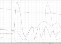
Figure 2 illustrates an impact. The sample rate is 1 each millisecond, so each dot represents one millisecond. The impact was made by hitting the end of a cylinder rod with a section of railroad tie. There were at least 25 combinations of impacts that were tried.
This impact was the final one. The red line is the actual position. The actual position is moving negative or retracting to reduce the difference in speed between the railroad tie and the end of the cylinder. The retract speed was about 21 in. per second. The blue line is the retract speed. The green line is the control output in volts. The control output is negative to retract the piston but goes to −10 volts after the impact. The pink line is the spool position. Finally, the black line is the measured force in pounds.
Until 6.705 sec., the force necessary to move at −21.6 in. per second was −183 lb. When the impact occurred, the force jumped to 4,149 lb. The control output went to -10 volts to reduce the force spike, but one can see it took many milliseconds for the valve to respond to the control signal and open up to −100%. The spool position stays negative for about 10 milliseconds, then jumps to slightly open at 8.9% even though the control signal is still at −10 volts.
The only explanations are that either the shock waves moved the spool, or the physical shock of the valve moving caused the spool to move. This is known to happen when the valve is mounted such that the spool travel is in-line with the hydraulic cylinder. The valve cannot possibly respond to sudden force spikes. The goal is to design systems that avoid them. This can be done by reducing the relative speed of impact or by adding compliance to the work piece or tooling.
Matching Kinetic Energy to Required Work
A question or demand that press manufacturers often have is about whether the press can have just one set of gains for every part produced. Usually, the answer is yes. The kinetic energy or speed at impact is the critical parameter. Each part is different and will require a different amount of energy to form it.
The goal should be to match the kinetic energy of the press to the work required to form the part. If this can be achieved, then there is little need for force control. But, this is seldom the case. If the press has too little kinetic energy, then the press will stall while pressure builds up to finish forming the part. If the kinetic energy is too fast, the excess energy will result in a force or pressure spike.
In the worst cases the material may not be formed right, or the die itself may suffer from excess wear or even be damaged. Both results are inefficient. In one test case with the railroad tie, the rod was stationary, so the relative impact speed was much higher.
As a result, the force spike went over 6,000 lbf whereas the maximum static force the cylinder could apply was 1,500 psi × 3.14 in2, or about 4,710 lb. Retracting the cylinder before impact greatly reduced the peak force. The goal is to match the kinetic energy of the press to each type of part that is made.
Press manufacturers often use a cushion or hydraulic cylinders below the die. The goal is to absorb shock. Often these cushions have marginal effect because the valves cannot respond fast enough. If the press is a mechanical press, then its vertical motion is sinusoidal. If an absolute encoder is attached to the crank, then the position and velocity of the top die can be calculated by the cushion control, allowing the cushion control to anticipate the impact by starting to retract before impact.
The cushion control can then adjust the motion of the cushion to increase or decrease the peak force either by increasing or decreasing the retract speed, or by increasing or decreasing the starting position when retracting. The choice depends on how far or deep the work piece must be formed. This relies on the fact that the mechanical presses velocity decreases as it approaches the bottom of the stroke.
If the top and bottom of the press are controlled by the same hydraulic motion controller then it is easier to synchronize the ram and cushion and make fine adjustments to positions and velocities, so the peak forces remain constant. This requires the ability to adjust on-the-fly using the past to adjust for the future. Automatic adjustments are also required because presses heat up during operation, causing the dimensions of the press to change slightly. Even a few thousandths of an inch can make a big difference in the peak force.
Fine Points about Control
Normally proportional, integral, and derivative control is used to control force. A good way to start is to move the actuator against a load in open loop so the system is at maximum force. Then start with very little force proportional gain and increase it slowly until the force comes down to the force set point. There should be no motion while trying to get control using the force proportional gain. If there is some internal leakage, then a small amount of integral gain may be required. Start with small values. Next, it is useful to cycle the force set points between two settings to adjust the force gains. The force derivative gain is handy for reducing minor force overshoot. Use feed forwards if available to help the actual force track the target force when transitioning between two forces.
Finally, test how the force control works when making the transition from position control to force control. A safe way to do this is to use an open loop command with a small output to move the actuator to make contact at a reasonable speed that will not cause the force to overshoot too much. Adjust the gains for optimal response, then then make the open loop move at higher speeds until the impact causes too much force overshoot. Now the maximum impact speed is known. Lower speeds will result in less force overshoot. Some motion controllers have a procedure for optimizing the force closed loop gains which reduces commissioning time greatly.
Next month’s article will be about leveling presses where usually four actuators are used to control a total force, but the hydraulic controller must also keep the four actuators from skewing so they will not mechanically bind, regardless of the force imbalance. Motion control, force control, and cascaded control loops will be covered.
Peter Nachtwey is president of Delta Computer Systems, Inc.


