Analyzing Challenges and Innovations in Electrohydraulic Pressure Control
Hydraulic motion control is a mature field, emerging during the late 1920s in automotive power steering systems and later applied to flight controls for heavy bombers in the 1930s.
During a period after World War II, control of hydraulic servo-mechanisms was a field of intense study at the Massachusetts Institute of Technology's (MIT) Dynamic Analysis and Controls Laboratory, and Herb Merritt’s “Hydraulic Control Systems” (1967) remains an authority on the subject matter today. Throughout this era, precision positioning of aerospace flight controls, and precision speed control of machine tool motors dominated the focus of research.
However, the academic study of hydraulic pressure control was largely ignored. In fact, Merritt dedicated less than a single chapter to these circuits in his text, which included a concise linear analysis of direct operated pressure regulation but forwent analysis on two-stage hydraulic pressure regulators.
At this time, electrohydraulic (E/H) pressure control was known to the art, but these mechanisms comprised a torque motor pilot characteristic of aerospace servo valves (US patent 2,767,689 filed by MOOG in 1953), and Merrit’s descriptions were reserved for spring energized valves in common use.
A year after Merrit’s publication, the first linear proportional solenoid comprising the now familiar frustoconical pole face was published in German patent law. And with the widespread availability of digital electronics by the 1980s, pressure control valves energized by these proportional solenoids began to proliferate in electronically controlled automatic transmissions both on- and off-highway.
Today, electro-proportional pressure control (EPPC) valves proliferate a broad variety of mobile hydraulic applications such as active suspensions, braking systems, traction control, load sensing and pilot valves, automatic transmission (AT) clutch control, and active track tensioning. However, after 40 years of commercialization and development, significant challenges remain when deploying EPPC valves in hydraulic systems as these devices often exhibit poor stability margin and unpredictable resonance that persists even after extensive tuning efforts.
It is accepted doctrine by many who practice the art that these valves are by nature troublesome, but that passable performance can be achieved after a lengthy cut-and-try process. Coupled with the recent focus on electrification, and a history of high-profile R&D failures in electrohydraulics, there have been marginal efforts in recent years to innovate at the valve component level.
Consequently, with advances in digital electronics spurring electronification and automation trends that pursue more efficient, precise, affordable, and adaptable operation, the limiting factors for the mobile hydraulic systems of tomorrow are likely to be the electrohydraulic components (and sensors) of today.
This article examines the dynamic challenges intrinsic to EPPC valves, how the electrification of a valve architecture originally designed for spring energization contributed to these challenges, and offers suggestions for improved EPPC valve architectures to address these shortcomings.
Assessing Challenges with Current Electro-Proportional Pressure Control Valves
Motivating this study of EPPC valves was the author’s experience analyzing AT clutch control systems for heavy mobile equipment, where performance variation and unpredictable instability events drive a tedious, ad hoc process when qualifying new transmissions, cause wear and warranty issues, and occasionally result in clutch failures.
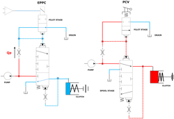
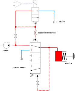
The hydraulic clutches in question were energized by a two-stage EPPC valve with the common architecture illustrated in Figure 1 below. Also illustrated in Figure 1 for comparative purposes is a two-stage pressure control valve (PCV) with spring energized pilot. The statement-of-work called for a linear system analysis to better understand, and resolve, unpredictable stability events.
When the linearized study failed to provide a clear resolution, the author conducted his own non-linear analysis. The resulting simulations demonstrated that two-stage EPPC valves sharing this architecture are fundamentally unstable, but conditionally operable due to a discontinuous non-linearity that disrupts energy exchange between the coupled pilot and spool stages. Specifically, this discontinuity is the limit of pilot travel as the poppet (metering oil flow from pilot chamber to drain) slams onto its seat.
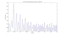
The result is a non-linear dynamic phenomenon referred to as a limit cycle — in physical terms the armature/poppet chain will ‘buzz’ continuously — slamming onto the poppet seat, reversing direction to open momentarily before once again slamming shut. These pilot stage limit cycles vary in frequency and magnitude, depending on operating conditions and system inputs, and influence the stability of the output spool-stage. Were this behavior to be observed by laboratory position measurement of the armature, it may very well be mistaken for dither generated by the pulse width modulated (PWM) coil driver.
This conclusion was supported by simulations that ‘virtually’ substituted the conventional 2-way pilot as illustrated in Figure 1 with a “bi-directional pilot” (drawn as a conventional 3-way spool) as illustrated in Figure 2.
This virtual test maintained pilot mass and flow area gradient and essentially allowed the pilot poppet to move ‘past’ the seat to reverse pilot flow to charge the pilot volume. By removing this discontinuity, energy exchange was not disrupted, but reversed, and the pressure output became unstable over the entire operating envelope. In fact, there was not any practical combination of parameters discovered that would globally stabilize the valve.
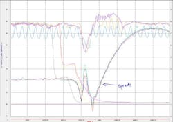
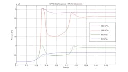
Figure 3 is provided courtesy of powertrain solutions developer Ker-Train Research. This graph illustrates a pressure-time plot of five AT clutch volumes each regulated by a common, commercially available size-10 two-stage EPPC cartridge valve. In this time sequence, two clutches drop out while three maintain pressure. One clutch volume oscillates persistently while the remainder experience unpredictable periods of oscillation of 9-12 Hz.
Considerable tuning effort with flow restrictions and pressure bleeds were required just to achieve the dynamic performance here displayed with limitations to shift time, and increased risk of flare and lock up events due to diminished coordination of on-coming and off-going clutches.
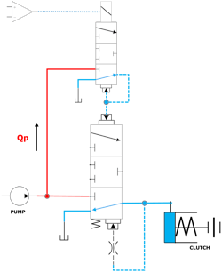
One convenient method to stabilize these two-stage EPPC valves, illustrated in Figure 4, deploys an isolation orifice between the pilot stage and spool. This configuration is commonly found in industrial valves, and in niche cartridge valves intended for the mobile market. If the application calls for slowly varying input signals, the response time is satisfactory. However, for applications that require rapid adaptation, the isolating orifice typically induces latency that is unsatisfactory.
Electrohydraulic Valve Instability: Potential Causes and Solutions
The following technical summary provides clarity into the cause of EPPC instability, as well as a proposed resolution. Illustrated below in Figure 5 is the two-stage EPPC architecture of Figure 1 in block diagram form. A first hydro-mechanical feedback loop is created with the pilot pressure acting through a pilot poppet seat area γ to create a feedback pressure force that balances the solenoid input force u.
A second hydro-mechanical feedback loop is created with the control pressure acting through spool feedback area β to create a feedback pressure force that balances an input pressure force created with the pilot pressure acting through a spool area α.
As illustrated, these two subsystems are coupled through a loop defined by the spool velocity multiplied by the spool input area α. The input-output relationship of each block, detailed descriptions of each parameter, and the derivation of mathematical models, are omitted for brevity.
The block diagram of Figure 5 can be reorganized into a more intuitive format by reconnecting the nested signal path as illustrated in Figure 6 and updating block H(s) by multiplying sα by inverse dynamics:
E-1(s)A-1(s).
Note that the second order armature/poppet dynamics [represented by A(s)] of the EPPC valve are dominated by the solenoid armature mass (b≈k≈0), and the pilot poppet dynamics of the mechanical PCV are dominated by the energizing spring rate (b≈m≈0).
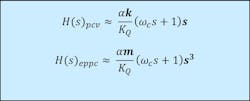
By transitioning from mechanical spring to solenoid energization, engineers gained computer control of output pressure but exchanged a very lightweight poppet element and stiff spring system for an inertial system dominated by the solenoid armature mass. This change in pilot dynamics is reflected in the feedback dynamics H(s) (Figure 7) where the triple derivative in the EPPC feedback path makes tuning a classically stable system an obstacle.
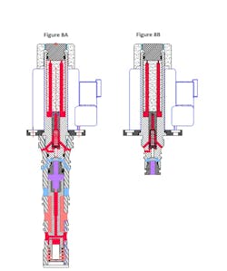
These insights endorse the development of methods to effectively isolate the armature mass from the valve dynamics without creating latency. One such method is to employ a ‘compound pilot stage’ by inserting a ‘transfer spring’ between the solenoid armature and pilot poppet as illustrated in Figures 8A and 8B.
This compound pilot (CPPC) method can be effective if carefully designed and tuned. Although the general concept is not new, the patent-pending architecture depicted in Figure 8 offers a simple and innovative construction due to its pressure-imbalanced pilot stage. The CPPC valve shown in Figure 8 also exemplifies a 'distributed damping' method, wherein the design and arrangement of moving elements form a network of dashpots through inherent geometries. Each dashpot is supplied from a high-pressure rail through a dedicated orifice, facilitating the independent tuning of the armature, pilot poppet, and main-stage spool elements.
This distributed damping method employs high-pressure oil to attenuate the adverse effect of entrained air. Critical to the innovation, these features are arranged and sized in such a manner that all forces balance regardless of supply pressure fluctuations. Prior compound pilot designs either rely on tank pressure to dampen the armature and pilot poppet elements or involve complex machining and assembly processes to balance these elements.
A properly designed CPPC arrangement allows for rapid adjustments of the pilot poppet to accommodate main-stage spool motion while the relatively high mass solenoid armature largely remains stationary. The solenoid actuator illustrated in Figure 8 is a modified version of the 037 Magnet-Schultz proportional solenoid and can be integrated with existing coil drivers.
Another method proposes a novel electric actuator, the details of which will be disclosed in future documentation, that is isolated from valve dynamics to a far superior degree than the CPPC approach of Figure 8. This ‘Servo Class’ Pressure Control (SCPC) valve comprises a new electric actuator under investigation that may be broadly applied to electrified hydraulic valve architectures. The two-stage SCPC valve architecture will employ the same distributed damping approach as the CPPC valve, enabling specific tuning of each independent moving component.
Comparing Electrohydraulic Valve Options
The following data plots provide performance characterizations of EPPC valves and comparisons to the proposed SCPC. While these are simulations only, results have correlated well with actual EPPC valve lab data.
Simulated conditions include oil temperature between 40-50 C, a 0.5 L fixed oil volume, and oil air entrainment between 2 and 15%. Each valve spool embodies a dual-stage or non-linear area flow gain so as to accommodate the high flows necessary to charge the oil volume rapidly and also converge to a stable operating point. This flow area strategy optimizes rise-time and settling-time at the expense of pressure overshoot.
The drain pressure was set to 120 kPa and pump supply to a constant value 3,050 kPa.
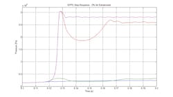
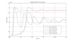
Data Plots 1 and 2 demonstrate step response characteristics of a production EPPC (of Figure 1). The step response for this valve was unstable over most of the performance envelope of 0-3,000 kPa. Any step between 900 kPa (green) and 2,600 kPa (red) for 15% air entrainment, and between 300 kPa (green) to 2,600 kPa (red) for 2% air entrainment would result in an unstable response.
Note that the responses at the red and green limits, while technically stable, are very non-linear and not suitable for functional operation.
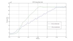
Data Plot 3 demonstrates ramp responses to a 1,600 kPa mid-point pressure at 2 and 15% oil air entrainment. These noisy, non-linear data plots reveal the rate limits for stable operation at this operating point. At 2% air entrainment, the ramp can be no faster than 250 ms without causing instability.
These three data plots collectively demonstrate that stable response of the EPPC is dependent on the pressure operating point, degree of air entrainment (volume stiffness), and rate of energizing input. Although it is beyond the scope of this document, there are other factors such as initial conditions that influence stability.
These variabilities reveal just part of the challenge of calibrating these devices in machines with a broad range of operating conditions, and why integration within future closed loop systems will provide a more considerable challenge.
Data Plot 4 demonstrates the pilot poppet limit cycles, discussed earlier in this document. Note that the limit cycles persist even as the EPPC valve is holding a set pressure.
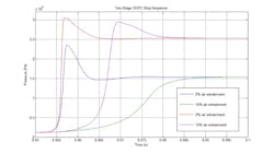
Data Plot 5 demonstrates step response characteristics for the proposed SCPC. This response is fast and stable across the entire operational range and for all inputs. Depending on the oil volume characteristics, the dual-stage spool area gain can be tuned for less overshoot at the expense of longer rise time. Note that the total rise-settling time falls between 15 and 35 ms depending on operating point and oil air entrainment.
While adaptation of the proportional solenoid was especially challenging for the two-stage EPPC architecture of Figure 1, it also compromised the performance of single-stage pressure control valves. By operatively coupling the mass of the solenoid armature to the spool, and with the EPPC return spring having a substantially lower rate than the energizing spring of the mechanical PCV, the second order “spring-mass” time constant of the EPPC is significantly reduced.
Consequently, the dynamic performance of single-stage EPPC valves is often quite poor unless the oil volume is very stiff, or very compliant. The proposed servo class electric actuator may also be applied to single stage pressure controls — effectively extending the second order time constant.
The following data plots for direct acting pressure control valves of EPPC and SCPC architecture were both produced with 10 mm spools.
Data Plot 6 demonstrates the simulated performance of a single-stage EPPC energized by a Magnet-Schultz 062 series proportional solenoid with the following specifications: 4 mm stroke; 112 N peak force; 160 g mass. This device exhibits a stable step response across the entire operational envelope, but performance is poor with settling time exceeding 250 ms at some operating points.
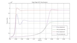
Data Plot 7 demonstrates step response characteristics for a proposed single-stage SCPC. This response is fast and stable across the entire operational range and for all inputs, with lower overshoot than the two-stage SCPC. Note that the performance for compliant (high air entrainment) systems is limited by spool flow forces, as is typical with single-stage valves.
With the anticipated shift in priorities from electrification to industrialization by the new presidential administration, the mobile equipment industry is expected to see an acceleration in the trends of electronification and automation. Advances in pump controls and flow-sharing technology will likely continue to improve machine efficiency.
But for the full potential of contemporary digital electronics and machine learning to enhance motion control to be realized, the mobile hydraulics industry will need to close the performance gap between the servo-hydraulic technology developed for industrial markets, and the economical electrohydraulic components that proliferate the mobile industry today.
This article was written and contributed by Michael Kriegsmann of Sunstream Scientific.
About the Author
Michael Kriegsmann
Chief Technical Officer, Sunstream Scientific
Michael Kriegsmann is Chief Technical Officer at Sunstream Scientific, a developer of advanced motion control products for industrial applications.

Leaders relevant to this article:
