Improving Compressed Air System Efficiency: Part 6
Your understanding of compressor controls and how to use them can be an important factor in how well your air system functions and the amount of energy it consumes. Unfortunately, many systems consist of a series of individual unit controls, with no provision for meeting the challenge of getting two or more compressors to operate together efficiently. Once compressors are purchased and installed, attention usually is limited to keeping the machines running — but not necessarily efficiently. Unless the output falls below the minimum acceptable pressure or the equipment fails for one reason or another, the compressor's controls are ignored.
Air compressor basics
Compressors don't make pressure; they pump volume. If a compressor is rated at a given pressure, that means it is constructed to safely contain that pressure. The controls limit the pressure relative to the configuration into which the compressor is pumping. If more volume is pumped into the downstream system than is removed by the users, the pressure rises. If more air volume is removed by users than is pumped into the system, the pressure falls. The job of the controls is to limit the pumped volume partially — or entirely — relative to the pressure set points adjusted on the controls. At full load, the compressor pumps 100% of its volumetric capacity and the controls perform no function.
Whether looking at single or multiple compressors, it is important that each compressor that is running should be optimized — this means pumping the optimum volume at the optimum pressure, or the maximum pounds of gas per minute at whatever pressure is accomplished with the least amount of energy. In addition, controls on compressors protect the equipment. They are usually integrally tied to safety alerts, alarms, or shutdowns. It is to your advantage to know what safety features are in the control system and how they function.
The vast majority of older compressors have few and relatively simple safety features — sometimes only encompassing high pressure and temperature shutdowns. Many newer compressors use microprocessors for controls and safety functions. Their control consoles include many more safety features and complex functions.
Control signals and signal location
Regardless of the type of control on the compressor, there must be a pressure signal to operate the control. The location from which the signal originates is critical to how the unit will function, how much energy it will consume, whether it will function with other compressors, and whether the desired performance will be achieved.
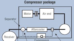
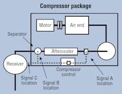
The idea behind control signals is to take a pressure from a location inside or downstream from the compressor and transmit it either pneumatically or electronically to the compressor controller. This signal interfaces with a pressure switch or transducer. In most compressors, the intent is to move air from the compressor air end downstream, to keep the pressure at the signal location at or between an adjustable set point (or set points) preloaded in the compressor controller. Many different potential locations for pressure signals are designated by compressor manufacturers, Figure 1.
Because the location will change the amount of energy the compressor consumes and the performance, the following should be noted:
• Compressor manufacturers have rated their performance based on packaged volume, pressure, and energy upstream of the aftercooler. Signal location is normally not discussed in the product literature. In some cases, performance is stated as "packaged," but this does not indicate what is in the package or where the signal is located.
• Some manufacturers have used signal location A for many years, but recently have begun to use location B.
• Other manufacturers state performance downstream of the aftercooler, interpolating the Dp across the aftercooler in the performance, even though the signal originates upstream of the aftercooler, and
• Many manufacturers use the same flow components in a package frame size to accommodate many capacity sizes - up to twice the size at the top of the frame as at the bottom of the frame. The effect of the components' Dp and the signal location will have a dramatic influence on performance. As the volume displaced in a given frame size increases, the Dp increases as a square function of flow, and the performance decreases.
One of the problems with installing the signal location upstream is that the quality of the air there is poor. The air is saturated with moisture and can be laden with lubricant. Both the water and lubricant will condense in the signal line, fouling the controls or transducer. Another prevalent problem is the effect of accumulating liquids in the control line — this can result in too high a pressure signal. Taking the signal from downstream of the aftercooler, at the separator, will reduce this problem by about 80%, but will still only delay the inevitable. Some manufacturers install signal line blow-outs, so that the lines can be kept clean on a daily basis. However, most have no means of correcting this problem other than disassembling the control lines or using a different signal from a dry, clean source downstream of the cleanup equipment.
Setpoints and deadbands
Compressor controls limit performance and/or displacement volumetrically, normally based on pressure. The controller will attempt to keep the signal pressure between the set points or at the set point. The set points are normally adjusted by the manufacturer's representative, and many operators and plant engineers are unaware of how these controls are set.
Most compressors use two set points. These represent the deadband of the unit controls. The deadband is the differential pressure between the highest pressure at which the compressor pumps the least mass of air and the lowest pressure at which it pumps the most mass of air. These two setpoints also normally represent the unload and load pressure. Adjusting the set points has a significant effect on how the compressor operates. The differential determines how the unit will respond to manage the pressure at the signal location.
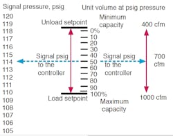
A typical set of control points on a pressure switch is shown in Figure 2. A 10-psig differential exists between the control set points. If the controls on this compressor are set to modulate, this implies that each 1-psi increment represents 10% of the capacity within the set points. IThe volume is at pressure. As the displaced capacity of the machine increases, the pressure will also drop. This means that the work energy is increased less than linearly.
Different types of compressors will respond in different ways. Rotary-screw compressors will displace between 40% and 100% of capacity. Thus, in the dead band modulating, 60% of the capacity can be displaced. If the unit were modulating at 50% of the dead band (as indicated in Figure 2), the compressor would be putting out 50% of the top 60%, or 700 cfm at 113 psig. Just before reaching the unload point, the unit will throttle back to 40%, or 400 cfm at 118 psig.
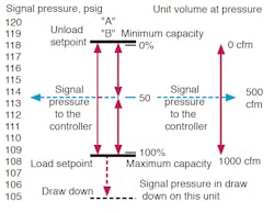
If the machine was in the load-unload operation, Figure 3, it would displace its capacity at variable pressures between the load and unload pressure. If the compressor is a positive-displacement design, the volume will remain constant from the load to the unload pressure at a rising pressure — thereby increasing density at rated mass or work energy available. In the case of recriprocating compressors, some are multi-step. In a two-step unit, the compressor will function at 0% and 100%, such as deadband A in Figure 3. Deadband B in Figure 3 is a three-step control which would displace 0%, 50%, and 100%. This would require either two pressure switches or a control regulator to perform the same function as two pressure switches. Most larger recriprocating compressors are capable of at least three-step operation. Some manufacturers offer five-step compressors, which displace 0%, 25%, 50%, 75%, and 100%.
If a unit would achieve its optimum mass at a given pressure, setting the unit controls below this point would achieve less than optimum performance. Setting the controls above this point would overload the drive motor. Careful planning of set points can determine how many compressors are necessary to achieve a particular result.
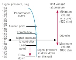
Some compressors, such as centrifugal designs, use a single setpoint controller. Most of these types of controls either attempt to maintain the signal pressure at the set point with modulating inlet and blow-off controls, or they operate load-no load within an adjustable proportional band related to the set point. The objective should be to keep the unit on a natural curve and out of the limiting controls for this type of base load compressor. As the signal pressure approaches the set points, the controls engage and move the operation off the curve and into the limited control range on the throttle line. In load-no load, the signal pressure rides the natural curve of the compressor, Figure 4.
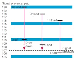
When the demand exceeds the capacity of a compressor, the pressure drops below the lowest set point below the deadband. This condition is called the draw down. This is an important condition to understand, because all compressors that are base loaded on their own controls or with a sequencer must be in draw-down before the next compressor becomes loaded. Figure 5 demonstrates a cascade of three compressors with two units in draw down.
If all of the compressors in Figure 5 were in modulation and the demand reduced, the signal pressure would rise and all compressors would throttle and remain part loaded. If the deadband spreads for each machine had a different Dp, the signal pressure that resulted would be a function of the way the set points were adjusted.
Settling on setpoints
Determining the best differential pressure between the setpoints presents an interesting problem. The wider the setpoints, the farther the system gets from optimum performance. Many service people set the controls at 10 psid or more to reduce potential cycling. The results are considerable pressure fluctuation and poor performance. By increasing the differential, there is less capacity per unit of pressure — which reduces the rate of response. Effectively using control storage will narrow the operating range of the compressor or compressors. Managing the operating range closer to optimum reduces the energy required without causing excessive cycling.
With centrifugal compressors, the market has been attracted to the concept of holding a single control pressure. For this to occur, the unit must be operated in modulation. Also, a misconception exists that this type of compressor does not need storage. Although there is some truth to this statement, there are a few problems associated with no capacity to store air and the use of single setpoint modulation. One is the need to always have more compressor capacity on line, either throttled or blowing off, so that negative event changes in the system can be supported without a significant drop in pressure. On the other hand, if a large demand event exits the system faster than the response speed of the compressor control valves, the compressor can rise to surge without adequate storage. Too frequently, the setpoint adjustment is set low in modulation to compensate. The results can be poor efficiency. Controls should not be used to compensate for poor system design. When the controls are slow to respond, the compressors are either too large for the event or there is insufficient storage.
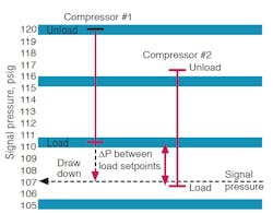
The ability to accurately hold setpoints in the controller will influence the differential between the load pressures of each compressor. This differential will determine how far into draw down a compressor must go before the next compressor loads or is influenced by the signal. It will also determine the lowest pressure which results in the system at the highest demand volume.
As an example, assume a system has four compressors (each with a 10 psig deadband) and the system's pressure switch drifts up to 3 psig. There would be 10 psi for the first base load unit and at least 3 psi for each additional compressor — more than 16 psi across the entire volumetric capacity of the compressors. Using less than 3 psid between load pressures means that the inherent drift in the controller could cause the compressors to fight each other, Figure 6.
Another consequence of too high a differential between load setpoints is that as more volume is required and the pressure drops, all of the base-loaded compressors will pump their capacity at lower pressures. Depending on where the deadbands are relative to optimum performance, this can mean considerable loss of mass per kilowatt for all units that are on. There have been systems where the setup of the deadbands was so inappropriate that the base load capacity would drop faster than the trim compressors could add capacity. The result was an inability to hold pressure on larger events. In this case, there was enough capacity, but the setup used gave the appearance of insufficient supply.
The accuracy of the pressure signal will also influence the results. Microprocessor controls receive an electronic signal from a pressure transducer. Most manufacturers use 62% accuracy; if the transducer is rated at 0 to 200 psig, there can be a 64 psig error across the range of use. This could cause erratic loading of an additional compressor — or make it difficult to operate a compressor or the whole system.
With centrifugal compressors, the signal problem can cause hunting of the inlet and blow off control valves as well as difficulty with more than one machine. Consequently, the use of more accurate devices is strongly encouraged. In higher pressure compressors, the accuracy of the control signal and receiver becomes more important. Improved accuracy costs more money, but it is insignificant compared to the demand and usage electric charges of operating with an extra compressor.
R. Scot Foss is president of Plant Air Technology, Charlotte, N.C., which specializes in air system auditing and design. This series of articles is based on his book, Compressed Air System Solution Series. To order a copy, click here.
About the Author
R. scot Foss
President

Leaders relevant to this article:
