A staff report
Air regulators are valves that reduce supply pressure to the level required for efficient operation of downstream pneumatic equipment. Once a system pressure has been selected to perform a task, a regulator provides constant pressure to the actuator, regardless of variations in flow and upstream pressure. Thus, it is important that a pressure regulator:
• supplies air at constant pressure regardless of flow variation or upstream pressure,
• helps operate the system more economically by minimizing the amount of pressurized air that is wasted. (This happens when the system operates at pressures higher than needed for the job),
• helps promote safety by operating the actuator at reduced pressure,
• extends component life because operating at higher-than-recommended pressures increases wear rate and reduces equipment life,
• produces readily controlled variable air pressures where needed, and
• increases operating efficiency.
Types of regulators
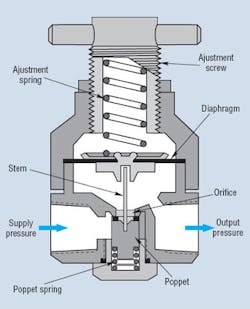
Unbalanced poppet, non-pilot operated — Figure 1 shows a simple regulator with unbalanced poppet; that is, it is not pilot operated. Normally, supply pressure enters the regulator and flows around the normally closed poppet, blocking flow.
Turning the adjustment screw to compress the adjustment spring forces the diaphragm down. It pushes the stem down and the poppet uncovers an orifice. As downstream pressure rises, pressurized air acts on the underside of the diaphragm, balancing the force exerted by the adjustment spring. The poppet throttles the orifice to restrict flow and produce the desired pressure. As downstream flow demand varies, the regulator automatically repositions the poppet in relation to the orifice. The spring under the poppet ensures that the regulator will close at no-flow. This regulator is non-relieving.
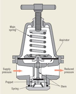
Unbalanced poppet, non-pilot operated with diaphragm chamber — The regulator in Figure 2 is larger (and more expensive) than the model in Figure 1. It also has a chamber that isolates the diaphragm from the main air flow to help reduce the effects of the abrasive air on the diaphragm, extending life.
An aspirator tube connects the diaphragm chamber and the outlet chamber. As flow through the regulator increases, the tube creates a slightly lower-than-outlet pressure in the diaphragm chamber. Pressure under the diaphragm deflects it downward, forcing the poppet farther away from the orifice. The adjustment spring extends to open the poppet orifice without significantly decreasing outlet pressure. The effect is the same as increasing the adjustment setting and, thus, reducing output pressure decay (droop) at higher flow rates.
This regulator’s much larger diaphragm area produces greater forces and, thus, displaces the poppet more with a given change in reduced pressure. It also increases regulator response and sensitivity. This style regulator has minimal droop as supply pressure varies. As discharge flow through the regulator is increased over its entire range, output pressure droops. Thus, it is important to set the regulator’s desired output pressure for normal flow conditions.
Balanced poppet, non-pilot operated, with diaphragm chamber — This regulator, Figure 3, has the same general internal construction as the previous type. However, it has a considerably larger orifice to allow for greater flow. In addition, to maintain good stability, the poppet is pressure-balanced; that is, the poppet sees the same reduced pressure on both top and bottom surfaces. Thus, the effects produced by reduced pressure fluctuations cancel out, and sensitivity and response are greatly improved. This very-large-capacity regulator has low droop.
With an exactly balanced poppet, the system-pressure/reduced-pressure ratio has no effect because the unbalanced resultant forces on the poppet caused by supply pressure are zero. However, these poppets are generally designed with a slight tendency to close. Therefore, a large increase in supply pressure forces the poppet closer to the orifice, throttling flow. This causes the reduced pressure to drop slightly.
Remote controlled, pilot operated, balanced poppet — In some applications, the regulator must be installed where it cannot be easily adjusted. The regulation and pressure setting mechanisms are then separated. A small air pilot line connects the regulator (in the air line at the point of use) to the remote setting mechanism, which can be mounted at any convenient location.
The remote setting mechanism is a small regulator that produces a control air signal. The signal is sent to a pilot-operated, balanced-poppet regulator, similar to the previous regulator except that the top is replaced with a short, pressure-tight bonnet to receive the control signal from the small remote setting regulator. Instead of working against a force created by a compressed spring, the pilot-operated regulator works against a force created by air pressure — that is, an air spring.
The air spring maintains a constant force on the upper side of the diaphragm of the pilot-operated regulator because the remote setting regulator holds the control signal at constant pressure. Thus, droop in this regulator is small.
Remote electrically controlled — This regulator controls pressure based on an electrical input signal and is described in the accompanying box, Electronic Pressure Control.
Internal, pilot-operated, balanced poppet — This regulator also uses the pilot-operated principle to produce a precision regulator. Both the pressure setting regulator and the pilot-operated regulator are combined in a single housing. The same force-balance principle applies as in the previous regulator.
With this regulator, some supply air bleeds into the cavity over the lower diaphragm and escapes through the nozzle. As increased air pressure on the upper diaphragm opens the flexible seat, the pressure above the lower diaphragm drops and causes the poppet to approach the primary orifice, reducing flow, and thus pressure. A bleeding-type relief seat vents through the center of the diaphragm. This regulator also has a safety-type relief valve above the pilot mechanism, which rapidly exhausts any very high overpressure.
Selection considerations
Selecting the best type of regulator for a specific application first requires a choice among these styles. Mini regulators are commonly the direct-acting, non-relieving type, while most standard regulators fall within the self-relieving, separate-diaphragm-chamber style. The next consideration becomes primary (unregulated supply) pressure versus desired secondary (output) pressure. Finally, desired air flow rate must be selected.
Adjusting screws are normally offered in two styles: tamper resistant, locking tee type or push-lock, plastic knob type. The first is best when a fixed operating pressure will be set once and left alone. The adjustable knob style (quite common on modular units) is the choice for general use, where the operating pressure can be easily adjusted without tools.
Regulators also are defined by body size (orifice flow rating) and connection size. Although several models may appear to be acceptable for any given air flow and pressure, a larger body size regulator will produce higher setting sensitivity and less droop than a smaller body model under the same set of operating conditions. An output pressure gage is essential, although many manufacturers frequently offer it only as an option. Mounting brackets are another useful option.
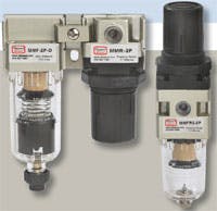
Manufacturers frequently preassemble filters, regulators, and lubricators (FRLs) to form combination units, Figure 4. They are packaged together as common body sizes with common connection port sizes. Interconnections may be via threaded nipples or modular face connectors. The modular connectors allow easy removal of components for servicing or cleaning. In addition, some manufacturers combine filters and regulators in stacked assemblies where the filter head becomes the regulator body. The components share common inlet and outlet connections, which makes the assembly compact.
Such packaged units, whether FR only or FRL, are practical choices for most industrial applications. The selection criteria are the same as with any of the individual components, except that the combined pressure and flow performance becomes the only consideration. When critical requirements dictate the use of specialty filters or precision regulators, the assembly probably must be made up of individual selections and connected with pipe nipples.
This information was updated from material appearing in the Fluid Power Handbook & Directory.
Electronic pressure control
As the trend toward automation continues, electronic control of pressure is a logical progression. Such electronic control of pressure has, in fact, become commonplace — both to allow automatic control of pressure for production machinery and for controlling pressure from a central location, even if the regulator is placed in an inaccessible or hard-to-reach location.
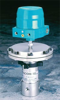
Instead of requiring operators to set pressure manually, a regulator may contain an electric motor that turns an adjusting stem until the desired outlet pressure is reached. Another design — sometimes referred to as an I/P or E/P transducer — accepts an electronic input signal (either E for voltage input, I for current) and produces an output pressure that is proportional to that signal. If the command signal (typically 0-5 or 0-10 V DC or 4-20 mA) calls for greater pressure, a valve in the regulator shifts to expose the outlet connection to the higher incoming pressure. If lower pressure is called for, a valve shifts to open and bleed the outlet to atmosphere.
With both the I/P and E/P designs, the device controls regulator pilot pressure, comparing this pressure to the command signal and acting accordingly to either decrease or increase outlet pressure, which in turn, increases or decreases the regulator outlet pressure. However, outlet pressure is affected by changes in flow, temperature, and other process disturbances, so to sense these changes and adjust the pilot pressure accordingly, the loop is often closed in a PLC or other control.
A third type of electronic controller closes the loop with an onboard microprocessor that accepts a signal from a pressure transducer located on the outlet of the regulator, compares that signal to the command, and automatically adjusts the pilot pressure to obtain the desired outlet pressure to compensate for any process disturbance.
If needed, the regulator can also supply an electronic signal representative of the process pressure for monitoring, data acquisition, etc. Versions that interface with digital controls are also available.
