Keeping a compressed air system clean ensures continued reliability, and precise pressure control keeps pneumatic systems operating efficiently. So, it's easy to see why a smart system designer will need to understand some basic concepts about airline filters and regulators.
Airline filters
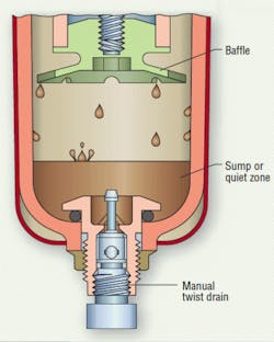
Airline filters come in two main types or styles: standard and coalescing. A standard airline filter, Figure 1, is responsible for two things in a pneumatic system: to remove particulate contamination from the air line and to eliminate water. Water is removed via a centrifugal swirling action inside the unit. This centrifugal action throws the water to the outside of the filter bowl, where it runs down into the filter's sump area, located under the filter's baffle, where it is collected. A common example of this type of action is a home washing machine during the spin cycle. Water is extracted from clothes by spinning them rapidly; centrifugal force flings water droplets through holes along the drum's wall.
The most common mistake made in selecting standard filters is oversizing them. A typical system has pipe or tubing sized for the port size of the actuator to be used. Therefore, the pipe size for the air preparation unit has been predetermined. This method of pipe size is right size specifies filters that are too large for the application, creating flows too low to effectively remove water from the system.
For solid contaminant removal, standard filters have element ratings ranging from 5 to 50 µm in size and are commonly made of a white polyethylene sintered material. These filters are used primarily at point-of-use and are selected and sized based on the application.
Manufacturers can supply flow curves to help select the proper filter for an application. In order to select a filter, it is necessary to know the system pressure, flow in scfm, allowable pressure drop across the filter, and what level of filtration is required.
Standard filters will typically come with a manual drain of some sort to remove the liquids collected in the filter sump area. Manual drains come in several styles, with some kind of threaded nut or knob to open the drain. The alternative is to select an automatic drain to remove the liquids. This type of drain typically employs a float to open the drain when the collected liquids reach a certain point in the bowl. If the user ever lets the collected liquid rise above the baffle, however, the filter's flow will pick this liquid up and send it back into the system.
Most bowls consist of a clear plastic material, typically polycarbonate, which allows the user to easily monitor the element's condition and the collected liquid's level. They include a bowl guard as a safety measure to protect the user in case the bowl sees excessive pressures, temperatures, or aggressive chemicals.
Metal bowls are another common option selected on filters for use in applications with higher heat, pressures, or chemicals not compatible with plastic bowl materials. Metal bowls are less userfriendly, however, as it is more difficult to view liquid levels and the element's condition.
Standard filter elements
Selection of the proper micron rating for a system is based on what types of components are being protected. The tendency is to go with the finest filtration available, but thought should be given to the effects this might have on system performance.
Standard control valves and actuators should be adequately protected with 40 µm filtration, while other devices with smaller internal clearances would be candidates for 5 µm filtration. The penalty paid for finer filtration is higher initial pressure drops — and therefore, lower flow ratings. To compensate for this, some manufacturers use larger element surface areas to improve the flow to pressure drop ratings, bringing it back up to the 40 µm level.
Coalescing filters
Coalescing filters are designed to remove liquid aerosols as well as hydrocarbons from the system. Common applications for coalescing filters are blow molding, gauging, food service, medical, dental, and pharmaceuticals, or anywhere else cleaner compressed air is needed.
Coalescing filters come in various elements ranges or grades, just as standard filters have various micron ranges. Most standard grades of coalescing elements will be capable of removing 99.9% or more of aerosol particles between 0.3 to 0.6 µm and all solid particles of 0.3 µm or larger. Overall filter efficiency ratings vary from 90% to greater than 99.999%, providing a wide range of capabilities to fit various applications.
These filters have a very high efficiency, but because the element's tighter matrix will have a higher pressure drop (and a shorter service life) than the same size standard filter, it is good practice to use a less efficient grade of element in the interest of service life and cost. In sizing a coalescing filter, the same basic information is required as in sizing the standard filters: flow, system pressure, and element efficiency.
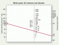
The simplest way to size a coalescing filter is to use a nomogram provided by the unit's manufacturer. The nomogram in Figure 2 is for a particular grade/efficiency of coalescing element with various housing and port sizes. With a coalescing filter, it is ideal to size it with an initial pressure drop of between 1 and 2 psi — this gives long service life and maximum efficiency.
The nomogram shows an application which has a 100 psi system pressure and 15 scfm flow rate. By drawing a straight line from the 100 psi spot through the 15 scfm flow on the flow line, the user will intersect the product line at an 11F filter. This is the minimum size unit that should be considered in this application. The next larger size might even be preferred, for lower pressure drop and longer element life.
It is important to note that a coalescing filter should be replaced when the pressure drop across it reaches 10 psid. At this point, a coalescing filter will be near the end of its useful life and is costing the customer money in wasted energy and filtration efficiency.
The cost of pressure drop
As solid contaminants collect on the inner surface of the coalescing element — clogging the inner matrix — the resistance to flow or pressure drop will climb. This pressure drop is seen in the system as inefficiency. Its cost is real and can be calculated. In many cases, designers and maintenance personnel do not see the value in element replacement, and the elements will be left in place long past their useful life.
A 5-psi pressure drop in a system may not seem like a great deal. But when considering energy costs, fixed operating costs, and so forth, over a 5-day work week with two shifts, a typical system could easily see a loss of $100 per week.
Pressure drop costs money in both energy costs and filtration efficiency. A good filter maintenance program will result in cost savings that will quickly pay back the replacement cost of the elements.
Typically, a coalescing filter will have a pressure differential indicator as a standard feature to indicate the pressure drop across the unit. These devices are generally of a mechanical style with a colorful indicator showing a 10 psid level. A more sophisticated version is available with an electrical differential indicator to supply feedback to a PLC.
One common practice is to always install a standard filter before a coalescing filter to prefilter the air — this removes large contamination, extending the service life of the coalescing filter.
Regulators
Pressure regulators take system pressure and reduce it for specific applications. When selecting a pressure regulator, the maximum inlet pressure, type of adjustment, reduced secondary pressure, and accuracy should all be considered.
Most pressure control regulators feature either a piston or diaphragm control construction and a balanced poppet. Piston regulators are more durable and robust, but are not quite as efficient at holding and maintaining a set downstream pressure. Diaphragm regulators are the most common style and do a very good job at maintaining the set pressure.
A third style is available as well, featuring a rolling diaphragm, which can give the long service life of a piston style unit with the accuracy of the diaphragm units. This style of regulator is used quite frequently in precision regulators.
Once the inlet pressure and secondary pressure are established, the correct regulator may be selected based on the manufacturer's flow curves. Once the required flow is determined for a pneumatic application, the regulator can be selected by using a flow chart.
It is important to note the inlet pressure on which each curve is based, because not all manufacturers will use the same inlet pressures. In recent years, the industry has attempted to standardize a primary pressure of 100 psi, with set secondary pressures of 90, 75, 60, 45, and 30 psi to make it easier to compare and select products.
After selecting the correct regulator, a few more decisions are necessary. The first deals with the regulator's adjustment spring range. Regulators will come with various spring ranges to offer the user better adjustment and control of the secondary set pressures. A common misconception is that a 60-lb spring can be considered a pressure limiter and will only give a 60 psi output. This is not true, as a 60-lb spring can supply an adjusted pressure of well over 60 psi. Remember — a regulator's pressure control spring is not a pressure limiter.
When selecting a spring range, a control spring should be selected that will place the desired set pressure as close as possible to the middle of the control spring's range. This gives the maximum amount of adjustability and control.
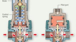
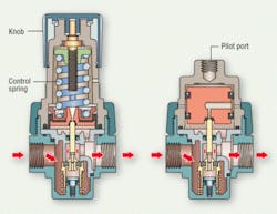
The next choice is to select an adjustment style: manual-or pilot-operated, as shown in Figure 3. Manualoperated units use a control knob or T-handle to adjust the regulator's output pressure. The non-rising control knob is the most common style used in today's market, because of its compact size and styling. The T-handle version is the more traditional style and is more commonly found on heavy duty applications.
A pilot-operated regulator simply replaces the standard control knob and spring with a pilot chamber. A small external regulator supplies a control pressure to the pilot chamber. Since most pilot operated regulators have a 1:1 ratio of pilot pressure to output pressure, a pilot pressure of 100 psi would deliver 100 psi out of the main regulator.
A standard industrial pressure regulator will have an accuracy of 2 to 4 psi, and if more accurate pressure control is needed, a precision regulator should be selected.
Precision regulators employ single or double diaphragm chambers and reduced poppet areas to improve performance. Precision regulators will typically also have a constant relief bleed improving the regulator's ability to relieve excess pressure. It also makes it more accurate, with an accuracy of within 0.05 to 0.5 psi.
For more information contact Parker Hannifin's Pneumatic Div., Richland, Mich., or call (269) 629-5000.
