Use compressed air to dry your compressed air
Many professionals estimate that about 95% of all compressed air systems can be classified as utility in nature. Utility air applications include common compressed air tools like blow-off guns, wrenches, grinders, hammers, spraying equipment, cylinders, etc. Utility air is well suited for these industries, and they most often use a refrigerated dryer to maintain recommended dew point of the air. Output from the compressor is typically processed through a refrigerated dryer that will produce a dew point ranging from 38° to 50° F.
Traditionally, utility air is processed through CFC-based refrigerated dryers before it is released to the plant's distribution system. These dryers require regular maintenance and have a life span of less than 10 years. Therefore, as a plant manager years ago, I decided to develop an alternative to CFC-based dryers.
The search for a better solution
I studied all the traditional refrigeration systems and found nothing I thought was applicable. I did, however consider water evaporation within a vacuum, which would dramatically improve the temperature shift of a typical evaporative system. However, all the systems I designed turned out to be nearly as complicated as a regular CFC-based system.
Therefore, I decided to use compressed air as the power source and ordinary tap water as the refrigerant. This permits an open-loop system — so instead of having to capture, compress, and recirculate a refrigerant, the open-loop system simply releases moisture and air into the atmosphere.
Using compressed air and tap water allows production of an extremely simple refrigeration cell with no moving parts and no electrical components. Coupling these Elliott Cycle refrigerators with an ordinary tubein- shell heat exchanger produces an effective refrigerated compressed air dryer that is environmentally friendly, has virtually no moving parts, and a rated life of 25 to 30 years.
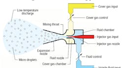
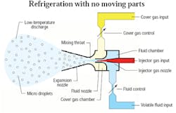
The Elliott refrigeration cycle, Figure 1, is based on fluid evaporation. Compressed gas is injected through an injector gas input nozzle which, in turn, drives a two-stage venturi. The first-stage venturi pulls a partial vacuum within the fluid chamber. A volatile fluid bleeds into the fluid chamber, drawn in by the partial vacuum. The rate at which fluid bleeds into the chamber is controlled by a fluid control — which is an adjustable needle valve.
Fluid atomizes into micro-droplets as it enters the chamber. This atomized fluid is then forced out through a fluid nozzle into the second-stage venturi. A dry gas is drawn into the cover gas chamber via the partial vacuum formed by the second-stage venturi. The cover gas and the atomized fluid are forced together as they pass through the mixing throat of the second-stage venturi. As the mixture enters the expansion nozzle, the atomized fluid rapidly evaporates, which, consequently, produces a low discharge temperature.
Keeping construction simple
Elliott Cycle refrigerated dryers operate in the same fashion as any other refrigerated dryer: compressed air is cooled in a controlled environment, and condensed water is trapped and periodically drained out. The principal difference is the simplicity of the Elliott refrigeration cycle and the durability of the equipment.
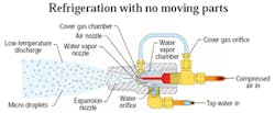
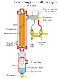
In practice, the refrigerator body, shown in sectional view in Figure 2, is made of machined PVC plastic with a plastic water vapor nozzle pressed into the core. The air nozzle, also made of PVC, is bonded into the core of the body. The space formed between the OD of the air nozzle and the core of the body is the water vapor chamber. The space between the OD of the water vapor nozzle and the body forms the cover gas chamber.
The water vapor chamber and the air nozzle have 18-in. NPT ports. A length of 18-in. plastic tube connects the cover gas port to the cover gas orifice. A compressed air inlet line mounted to a standard 14-in. compression street tee supplies compressed air to the refrigerator. The water inlet port fitting contains a small plastic orifice that meters the proper amount of water into the water vapor chamber. The outlet nose of the body is equipped with a 12-in. male NPT thread, which allows it to be screwed directly into the shell of a heat exchanger.
This refrigeration cycle can be used with different gases and fluids. The design presented here is specifically intended for compressed air-drying applications and, as such, can only be used with compressed air and water. Other gases and aromatic fluids can be selected to lower the discharge temperature of the refrigerator. However, components must be constructed of materials that are chemically compatible with the chosen fluids.
The discharge temperature is controlled primarily by the amount of water metered into the refrigeration unit. Too little water creates a sub-freezing condition in the discharge. Therefore, the rate of water introduced must exceed that which can be completely evaporated. Doing so prevents any chance of freezing within the heat exchanger and also improves thermal transfer.
The excess water forms micro-droplets that will normalize to the same temperature as the gas within the discharge. These cold micro-droplets then come in contact with the OD of the heat exchanger’s tubes and provide for high-efficiency thermal transfer.
Building a flexible system
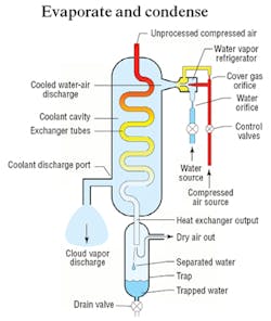
Figure 3 shows a schematic representation of how the Elliott cycle refrigerators can be configured with a heat exchanger and trap to form a compressed air dryer. Unprocessed compressed air is introduced into the air input, where it flows through the heat exchanger tubes, shown as a single S-shaped tube.
The refrigerator produces a cooled vapor cloud that is saturated with normalized micro-droplets and discharged into the coolant cavity of the heat exchanger. The vapor cloud is forced to flow through the heat exchanger — where it cools the outside of the exchanger tubes — and out the coolant discharge port.
When the unprocessed air comes in contact with the inside of the cooled exchanger tubes, its temperature drops. As the air temperature drops, its affinity for water vapor also drops. As the water is shed from the compressed air, it condenses onto the inside of the exchanger tubes. The condensed water runs down the inside of the tubes along with the compressed air flow and is discharged through the heat exchanger output.
The air and liquid water are routed through a separation trap, which forces the dry air into a series of turns designed to separate the liquid water from the air stream. The separated water collects into a small reservoir and is periodically drained through the trap’s drain valve. The now dry compressed air flows through the output of the trap and is introduced to the distribution system.
The sheer simplicity of a system such as this allows flexibility when designing the balance of the compressed air system. In addition to having no moving parts and requiring no electrical components, the system’s entire exchanger and trap can be constructed of Schedule 40 welded piping components. Doing so produces a durable piece of equipment with a life expectancy that better matches the compressors it serves.
A sectional view of an Elliott cycle dryer designed for small, packaged compressors is shown in Figure 4. The body of the heat exchanger is constructed from a piece of Schedule 40 steel pipe with forged steel fittings and mild steel tube plates. The assembly features all-welded construction for longevity and reliability. The internal tubes of the exchanger are made of Type 122 copper and bonded to tube plates using a proprietary process.
The refrigerator mounts into the 12-in. female NPT port at the top of the heat exchanger shell, and the coolant discharge is located at the bottom of the shell. The trap assembly is of the same construction style as the heat exchanger — all-welded Schedule 40 pipe components with forged steel fittings. The input nipple of the trap is specifically matched to the reducing bushing that makes up the heat exchanger output.
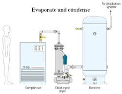
Units in the 25 through 200 scfm range (5 to 40 hp) are generally mounted directly to the compressors or receivers that they service. Dryers 250 scfm and larger (50 hp and up) are generally mounted to an integral basetrap assembly and are stand-alone units, as shown in Figure 5.
The dryer in Figure 5 is placed between the output of the compressor and the input of the receiver. This arrangement produces a clean, simple installation and is the preferred arrangement for an Elliott cycle dryer for systems using a rotary screw compressor. For smaller, reciprocating compressors it is generally recommended that the dryer be located on the output of the receiver and after the master pressure regulator, if used.
Because the Elliott refrigerator produces a vapor cloud as the coolant, the effective cross-section of the heat exchanger must be limited to a section that the vapor discharge can effectively penetrate. This cross section limits the construction of the heat exchangers to units that have approximately 500 scfm drying capacity. To manufacture larger capacity dryers, 500 scfm heat exchangers are ganged together on common manifolds. Dryers are manufactured in this configuration for flows to 3000 scfm (six 500-scfm heat exchangers). For dryers more than 3000 scfm, a secondary, bolt-together manifold is manufactured for grouping smaller units together. As an example, a 5000-scfm dryer is assembled utilizing two 2500-scfm units on common input and output manifolds and with common controls.
Brian S. Elliott is chief of engineering at Air Options Inc., Houston, and author of Compressed Air Operations Manual, published by McGraw Hill. For more information call (713) 721-9619, e-mail [email protected]., or visit air-options.com.
