Controlling valves in hazardous locations
By Robert W. Altonji
President
PneuMagnetic LLC
Quakertown, Pa.
Solenoid valves are arguably the most common type of on/off flow control valve. They come in a tremendous variety from many manufacturers. They are compact, easy to interface with control systems, and operate at high speeds over long distances. And because a magnetic field penetrates the valve body to open and close the flow blocking element, there is no need for a fluid seal between the inside of the valve and the external mechanical drive element.
But in hazardous applications electric valve operators, by their very nature, are potential fire and explosion initiators. That’s not to say that electric valves cannot operate safely in hazardous areas. But design requirements are exacting and can be expensive. See the accompanying sidebar, “Fire and explosion protection systems,” for more details.
Pneumatic advantages
All-pneumatic valves for fluid control are simple and highly reliable. They solve the fire and explosion hazard problem by removing the hazard initiator: electricity. This makes them desirable for use in hazardous locations.
Control signals come from pilot valves located in non-hazardous areas. Small-diameter flexible tubing, either metallic or plastic, carries the pneumatic signals, so space requirements in and around equipment are minimal. Control-system integrity is also high with pneumatic operators because control lines are not as susceptible to compromise or likely to produce secondary safety impacts.
Pilot valves are considerably less expensive than intrinsically safe (IS) barriers and, with today’s ultra-clean control system air supplies, they can often be mounted inside electric control enclosures without posing corrosion issues for the electronics. In addition, manifold-mounted pilot valves provide high density and small footprint for multi-valve applications. Even larger-Cv pilot valves typically take up less space than a bank of IS barriers. Pilot valves do not have the restrictive wiring requirements of IS barriers which yields even more space savings. Added up, pneumatics becomes a cost-effective solution to valve installations in hazardous applications.
Pneumatic actuation is also well suited for continuous valve cycling. Unlike electric coils in which excessive heat from rapid cycling is deadly, pneumatics can cycle continuously with no ill effects. Absence of coil heating can be a benefit in applications that have thermal restrictions for the process fluid or surroundings. In addition, there is no hum, as with ac coils.
Although most solenoid-valve suppliers sell pneumatic versions of their electric products, the breadth of offerings is typically much narrower, especially in sizes smaller than 1 to 2 in. Most tend to be larger than electric valves of the same capacity.
The actuator, mounting, and sealing differentiate pneumatic process valves. Type of actuation determines how pneumatic pressure and flow are converted into mechanical operation of the valve. For low-Cv valves, strokes are short and convoluted diaphragms are often used to provide force and stroke directly without any sliding action. Larger-Cv valves, which use piston actuation, are for applications that require longer strokes or a smaller package.
Probably the biggest drawback to pneumatic process valves is that most require a mechanical link between the pneumatic actuator and flow-control element. And this element requires a seal, commonly a packing or O-ring, to keep process fluid inside the valve from escaping to the environment. Bellows and diaphragm seals are also used, but these tend to be costly and bulky.
Magnetic actuation
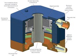
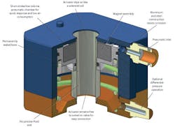
Process fluid seals are a prime source of environmental contamination and present a secondary safety hazard. Magnetically coupled valve actuators eliminate this problem. These self-contained pneumatic-magnetic devices use pneumatic force to shift a tubular-shaped permanent magnet which, in turn, drives the valve armature with the same magnetic force as a solenoid coil normally provides.
Because a magnetic, not mechanical, connection shifts the valve, there is no need for a packing or fluid seal. This eliminates leakage issues inherent in other valves.
An inexpensive air pilot using a small-diameter, flexible pneumatic line shifts the valve – much the same as with traditional pneumatic-actuated valves. No electricity, field wiring, conduit, or intrinsically safe barriers are required.
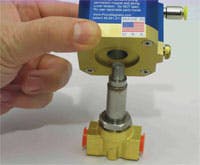
The PneuMagnetic actuator from PneuMagnetic LLC, for example, is a drop-in replacement for the OEM coil on direct-acting solenoid valves and requires no valve modifications. It provides the same powerful on/off magnetic field as solenoid coils with the same control of flow.
In fact, dc solenoid valves typically cannot handle pressures as high as their ac versions. Advances in rare-earth magnets let Pneu-
Magnetic actuators provide the same valve pressure performance as equivalent ac versions. Rated life is at least 7 million cycles.
Because PneuMagnetic actuators fit directly on solenoid-valve bodies, this makes a wider range of valves available to the system designer. For instance, actuators currently available fit several major brands of solenoid valves.
Hybrid systems
Another option is to combine the benefits of intrinsic safety and pneumatics. This can be a robust and cost-effective way to control process valves in hazardous locations. Several suppliers offer IS pilot valves and IS I/O systems that bring control signals deep into the physical plant. They provide high-speed, long-distance signals to the process valves. Pneumatic outputs make a final short connection to the process valves and, thus, provide low-cost valve actuation and control.
Combined with magnetically coupled valves, this hybrid design takes the best from both technologies and combines them into an overall system that, in many installations, offers the highest performance at the lowest installed cost.
Making choices
When using valves for hazardous environments, design choices come down to balancing performance, cost, and reliability. Explosion-proof (EX) and purged systems are still the only real choices for high-power devices like motors. But for valves, they are costly to install and maintain and severely limit flexibility for future changes.
Intrinsic safety solves the space issues of EX components and provides significant installation savings for long runs and multi-drop valve applications. Cost per node for barriers and IS-rated valve coils can be high but it provides high-speed, long-distance valve actuation and simple field wiring.
Pneumatics provides the flexibility and ease of installation of IS without stringent wiring requirements and at a lower cost per node. Pneumatic system integrity is high because with no electricity in the hazard area, there is no fire/explosion initiator.
Magnetically coupled actuators on solenoid-valve bodies provide pneumatic operation of packless valves. It provides the safety and economy of pneumatic valves, as well as the diverse selection of solenoid valves, without process fluid seal-leakage problems. Magnetically coupled actuators also let designers use the same valve body for both hazardous and non-hazardous applications by exchanging the coil for the magnetic actuator. This saves money because separate inventories do not have to be maintained for hazardous and non-hazardous valve applications.
For more information, contact PneuMagnetic LLC at (888) 610-4804 or visit www.pneumagnetic.com.
| Fire and explosion protection systems Explosion proof Solenoid coils rated for EX service cost more than standard versions. In addition, EX technology consumes a relatively large amount of space because every valve must have a rigid, sealed pipe conduit connection for providing electrical power. This conduit must be routed through the equipment and plant until it terminates in a non-classified area. And conduit must carefully connect to the valve coil so there is no undo strain on the valve bonnet. This often requires a hazard-rated slip joint fitting or expensive flexible conduit at the valve-coil connection. Wiring within the conduit must be sealed with a flame barrier (concrete-like filler seals wires within its own special conduit fitting) to prevent flame propagation. So, in addition to the process fluid pipe, there is a second pipe/conduit to contain the wiring. Further, EX systems cannot be serviced without securing the substances which make the area classified. This puts the system process out of service during maintenance. Purged systems This avoids the need for total system sealing, as with EX circuits, but still requires conduit as well as a secure and monitored purging system. As with EX designs, purged systems cannot be serviced without securing the substances which make the area classified. Intrinsically safe There is a cost trade-off, however, because IS valve coils, barriers, and enclosures all add significant costs. In short-distance applications with few valves, IS may be more expensive than EX systems. For long runs, crowded physical space, or multi-drop valve applications, the savings can be substantial. From the outside, an IS system looks as simple and uncluttered as a non-hazardous installation. Control equipment is located remotely in non-classified areas and field wiring to valve coils uses plastic-jacketed cable about the size of LAN cable. Valve coils can be slightly larger than standard coils, but otherwise, the field wiring looks unremarkable. There are, however, special wiring requirements.
The design and installation of IS systems requires careful consideration to prevent mixing of IS and non-IS circuits. Different IS circuits must also be protected from each other, though this is often fairly straightforward. Typical installations have a separate enclosure (which does not have to be rated for classified areas) for housing IS barriers and wire terminations. Wiring within this enclosure must be secured so that loose wires from protected and non-protected sides of the barriers cannot touch each other. The goal is a complete physical and electrical barrier between protected and non-protected circuits. Servicing IS systems requires special care to maintain all the protection requirements. This is especially true of the integrity of the wiring-system physical restrictions. Unlike EX systems, IS systems can be serviced without having to secure the substances which make an area classified. |
| Classifying hazards Areas are classified by the hazardous substance (such as gas or dust); the exposure probability (for example, flammables always present); and the flammable material. Different protection levels are required based on this classification system. Also consider non-electrical hazards, specifically potential environmental contamination from process fluids. When specifying valves to control noxious or hazardous fluids, pay attention to potential leakage from valve process seals, typically packings around mechanical control elements. These leaks can result in anything from nuisance housekeeping issues with water or oil to full blown safety hazards from ammonia or chlorine leaks. Long term system integrity is also important. Consider how maintenance will impact system integrity and safety, and worker training and skill-level requirements. And even if installed and maintained per code, what is the likelihood that incidental impact, abrasion, or chemical attack will affect long term safety performance? |


