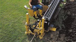
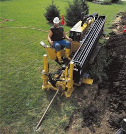
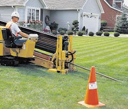
A technique surprisingly similar to arthroscopic surgery has swept the construction industry — directional boring. Instead of cutting a patient open to gain access to organs and tissue, arthroscopic surgery makes a small incision at a precise location and uses tiny instruments to perform the medical procedures needed. Like arthroscopic surgery, directional boring cuts only a small entryway in the earth's surface at the work site. It then creates an underground channel that eventually will contain electrical or communications cable or piping for water, gas, or sewer service.
With conventional trenching, the site first must be excavated by removing earth to a specific depth for the entire length of the run. The cable or pipe then is laid into the open trench, the earth is pushed or scooped back into the trench, and finish work, such as compacting and landscaping or paving, is performed. Needless to say, these are time-consuming and labor-intensive tasks.
As with arthroscopic surgery, directional boring is much less intrusive, takes less time to perform, and can cost less than conventional techniques. This proves to be especially beneficial when working in congested or environmentally sensitive areas. Another huge benefit — in addition to those just cited — is that when cable or pipe must be laid under a freeway, directional boring can get the job done with absolutely no interruption to traffic.
Early directional boring machines had to be towed to a location and set up. Newer machines, however, are self-propelled and self contained. In a typical machine, a hydraulic system provides power for a pair of track drive motors, a stakedown system, and all boring functions. Once at the work site, an operator need only connect the machine to a source of water. So, in a way, these machines combine new techniques with old — you could say that they make house calls and then conduct underground arthroscopic surgery.
Mechanics of directional boring
Directional boring starts by penetrating the earth with a drill head where the cable or pipe eventually will come out of the ground. The machine then pushes the drill at an angle deeper into the ground. Sections of drill rod — each typically ten- or 15-ft long — are added as the drill head advances deeper into the ground. The front of the drill head has an angled plate, or bit. This bit acts as a rudder to steer the drill head according to its orientation. For example, if the drill head is oriented with the inner face of the bit facing down, applying thrust to the drill will force it deeper into the ground. If it is facing to the left, the bit will direct the drill head to the left. Direction of the bore, then, is controlled by maintaining proper pitch of the drill head, which can navigate the drill rod through a minimum bend radius of less than 100 ft.
Because the bit will always direct the drill head in the direction its inner surface is facing, simply pushing the drill head into the ground tends to create a curved channel. To create a straight channel, the drill is rotated while it is pushed deeper into the hole. In essence, then, the drill head actually cuts in a slightly helical path when boring a straight hole. A battery-powered transmitter inside the drill head sends a signal to personnel above ground so they can monitor the location, depth, and orientation of the drill head.
To aid boring, any of several drilling fluids — known as mud — is pumped through the hollow drill rod to the drill head. The mud mixes with the material surrounding the drill head to form a slurry. The slurry acts as a lubricant between the channel and the outer circumference of the drill rod behind the drill head.
Once the drill head emerges from the ground at the target area, it is removed from the drill pipe and replaced with a reaming tool. The utility cable or pipe is attached to the free end of the reaming tool, and the machine begins pulling the drill pipe back out of the ground. As it pulls, the machine also rotates the drill pipe, and with it, the reaming tool. The spinning reaming tool enlarges the diameter of the underground channel to accommodate the utility cable or pipe. It also pulls the cable or pipe with it as it retracts toward the original entrance to the channel. When it eventually reaches the machine, the cable or pipe is already in the ground, right behind the reaming tool.
Pressure compensation, load sensing
All major functions of these machines are powered and controlled by hydraulics. To understand the role of hydraulics, we'll examine a mid-sized machine designed and built by a major mobile equipment manufacturer. Power starts with a 60- to 65-hp diesel engine driving a pair of tandem-mounted axial-piston pumps at optimum engine speed — generally around 2500 rpm.
Mounted to the engine is an Eaton model 70422 axial-piston pump, which powers all hydraulic functions on the machine except drill rotation. These include propulsion, stakedown, drill thrust and pullback, and the mud pump. This pump features pressure compensation to regulate pump displacement when system pressure reaches the compensation pressure. When this occurs, the compensator circuit reduces pump displacement to maintain this pressure.In addition to pressure compensation, this pump also features load sensing, which matches pump output to load requirements. Pressure compensation destrokes the pump only when pressure reaches a maximum (compensation) pressure. Load sensing, on the other hand, closely matches pump output to load requirements at pressures slightly above load pressure. This differential is the load-sensing pressure. In the case of the machine, load sensing pressure is 400 psi.
For example, consider the track drive circuit, where the pump supplies hydraulic power to a pair of gerotor-type motors to propel the machine. Without load sensing and the pump running with the vehicle stationary, the compensator would destroke the pump to maintain full system pressure — in this case, 3400 psi. However, load sensing would destroke the pump at a much lower pressure — in this case, 400 psi, the load-sense pressure. If the machine was moving down a slight grade and needed only 1000 psi to maintain maximum speed, the load-sensing circuit would destroke the pump to maintain system pressure at 1400 psi — again, the required load pressure plus the 400-psi load sensing pressure.
An additional benefit of load sensing in this application is that it enhances manual control. Without load sensing, operation of a system maintained at the relatively high compensation pressure can be jerky when a valve opens. This is because when a valve opens, fluid flows into the actuator more smoothly when the pressure differential between system (upstream) pressure and load (downstream) pressure is only 400 psi — as opposed to as much as 3400 psi without load sensing. The high pressure differential creates a pressure surge or shock wave when the valve opens suddenly. With load sensing, system pressure stays within 400 psi of load pressure, so the pressure surge is much less dramatic.
Drill rotation pump, LSHT motor
Of the two hydraulic systems in the machine, the drill rotation circuit is by far the simplest. It is powered by an Eaton Model 72400 pump driving an Eaton Series 6000 Geroler-type low-speed/high-torque (LSHT) motor. Drill rotational speed is controlled manually by the operator through a mechanical push-pull cable that controls flow by varying the pump's swashplate angle. Pressure is limited by the circuit's relief valve.
Directional boring must be performed over a wide range of speeds. It has been found that an experienced human operator provides the best means of closed-loop speed control to maximize operation, production rate, and energy efficiency. More elaborate controls would have added cost and complexity to the system and not done as good a job as manual control.
The geroller-type motor drives the drill chuck though a gear box that reduces drive speed to less than 150 rpm. More importantly, though, the gearbox has a hollow output shaft. The machine pumps mud through the center of drill rod, so the rotation mechanism needs a flow passage through it. A LSHT motor with a hollow output shaft could have served this purpose, but the geroller-motor/gearbox proves most practical. A hollow-shaft radial-piston motor, for example, would have accommodated application parameters, but its large OD would have kept it from fitting into the space available.
Thrust and pullback
The most important function of any directional boring machine is its ability to push drill rod into the ground and pull it back out again. The machine uses a 3½-in. bore cylinder with a 2-in. rod and 65-in stroke to accomplish this essential task. But because drill rod sections are 10-ft long, a 65-in. cylinder stroke obviously will not travel the entire length of a drill rod. To overcome this limitation, the effective cylinder stroke is doubled by incorporating a leaf-chain mechanism — the same concept used in forklift trucks. However,two chains are used with the boring machine: one to double the cylinder's extend stroke and one to double its retract stroke. Two are needed because the chain can only pull the rod carriage, not push it. One end of each chain is fixed to the machine's framework, the other end is attached to the rod carriage.
The thrust/pullback cylinder is mounted so that extension pulls the drill rod out of the ground. This is done because pulling the drill rod from the ground requires greater force than thrusting it in. When pulling drill rod out of the ground, the thrust stroke resets the rod carriage at essentially no load for the next pullback stroke. The 2-in. diameter rod displaces roughly one-third of the rod-end volume, so the reset stroke executes quickly.
When thrusting drill rod into the ground, the pullback stroke resets the rod carriage for the next thrust stroke, again, at essentially no load. However, the pullback stroke requires pumping fluid to displace the entire cap-end volume of the cylinder. Potentially, then, the machine could exhibit a long dwell period while the carriage resets.
To shorten unproductive dwell periods, manufacturers often incorporate a regenerative circuit. Instead of routing fluid exiting the rod end of the cylinder to tank, the regenerative circuit routes rod-end fluid to the cap end. Therefore, fluid volume equal to the rod volume is all that is needed to extend the cylinder under no load. Reducing fluid volume to retract the cylinder, in turn, reduces retraction cycle time.
Hydraulic track drive
An important feature of any self-propelled directional boring machines is the mobility provided by the hydraulic dual track drive. The mid-size machine we've been examining is typical in that it uses a pair of hydraulic motors in a skid-steer arrangement for its track drive. But the machine is only about 3-ft wide so it can reach relatively inaccessible areas. However, stability is important when travelling over rough or uneven terrain, so track width can be increased about one ft when the machine need not be set to its minimum width.
Track width is controlled by a double-acting hydraulic cylinder. The cylinder extends or retracts a track that is guided by a pair of linear bearings that keep it parallel to the stationary track. Using pair of cylinders to move the track would have required incorporating a flow divider and additional components into the system. The arrangement in use is simple, reliable, and more cost-effective than a two-cylinder arrangement. As with the drill rotation assembly, the track width adjustment assembly blends the strengths of hydraulic design with those of mechanical design.
Stakedown and outrigger
Once the machine has moved to the work site, it must be secured in place. The machine applies more than 5 tons of thrust and over 8 tons of pullback force to the drill rod. Therefore, some means must exist to counteract this force — especially when you consider that the entire machine weighs substantially less than the force it can generate. Otherwise, instead of pushing the drill into the ground, the machine's force could push it away from the hole.
The machine's stakedown system incorporates a pair of augers, each driven by an Eaton Series 2000 Geroler-type LSHT hydraulic motor, and a pair of hydraulic cylinders. The double-acting cylinders, each with a 1½-in. bore, 24-in. stroke, and 1-in. rod, apply a constant force to push the augers into the ground while the hydraulic motors rotate them.
As designed, the stakedown system uses the cylinders to make the augers self tapping. If the system relied only on the weight of the components for downward force, the augers might simply drill a pair of holes into the ground under less-than-ideal soil conditions. This would not provide as much stability as actually threading them into the ground and would also create additional work at cleanup time.
On the back of the machine, an outrigger bar provides secure support. A pair of cylinders extends downward to press against the ground and lift the rear of the machine off the ground. But the greatest support comes from the stakedown system at the front of the machine.
Additional functions
To keep the machine self-contained, hydraulics is used for functions normally reserved for electromechanical drives. For example, a hydraulic motor drives the 25-gpm mud pump that supplies drilling fluid to the drill head or reamer. This pump generally runs during boring operations but requires hydraulic flow rather than pressure. The main drill rod cylinder, however, calls for high pressure instead of high flow. This allows the mud pump and main cylinder to be supplied simultaneously from the same pump without degrading each other's performance.
Hydraulics also accomplishes an important safety feature that disables the drill rotation and thrust/pullback circuits unless an operator is seated at the operator station. A normally closed solenoid valve is controlled by a switch mounted under the operator's seat and blocks flow to hydraulic circuitry that operates drill rod functions. When the operator sits on the seat, the switch opens the valve, enabling downstream valves to operate. If he or she moves from the seat, the hydraulic system is again disabled.
The cartridge valves are used extensively on the directional boring machine. They enable the combination of several valves and valve functions into a single manifold. These manifolds reduce the amount of hose, tubing, and fittings required and eliminate many potential sources of leakage. Cartridge valve groupings are also more compact than line-mounted valves and promote neater, cleaner designs. Most of the hose on the machine is designed for service in mines and protected by abrasion-resistant sleeves.


