Tips for specifying pneumatic valves
Directional-control air valves are essential building blocks of pneumatic circuits. But there is a wide variation among different valves, ranging from the number of positions, flow paths, and number of ports they offer to how they are actuated, mounted, and controlled.
Based on our experience over the years designing pneumatic systems, here are some guidelines for specifying valves that give the best performance and efficiency in a given application.
Sizing basics
One key consideration is how much flow a valve can deliver to an actuator. This is usually rated in terms of coefficient of velocity, or Cv. It is generally used to compare flows of different valves: the higher the Cv, the greater the flow.
To match a valve and cylinder, the following equation gives the Cv (valve flow) required for operating a given air cylinder within a specific time interval.
Cv = (A × S × a × Cf) ÷ (t × 29)
where A is cylinder piston area
(π × r2), in.2;
S is cylinder stroke, in.,
t is time, sec,
a is a pressure drop constant,
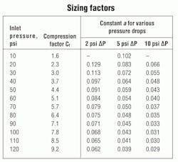
and Cf is compression factor. These last two are listed in the accompanying “Sizing factors” table.
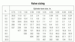
Another method for selecting valves is to use the “Valve sizing” chart. It indexes valve Cv against cylinder bore size and gives the resulting cylinder speed in inches of stroke per second. It assumes a pressure of 80 psi and ΔP = 80%.
To account for various losses in all pneumatic systems, experts generally recommend oversizing the valve by at least 25%.
And keep in mind that many other factors contribute to the performance of a cylinder. These include: quantity and type of fittings leading to the cylinder, tube length and capacity, cylinder operating load, and air pressure.
You can attempt to calculate Cvs for every component and place a value on the other contributing factors. But it is often more practical, not to mention faster, to follow a valve manufacturer’s guidelines when sizing valves.
For example, a sizing table for various Mead air valves (available at http://bit.ly/hp0312mead) relates valves to cylinder bore sizes between 0.75 and 6 in. The cylinder operating speed resulting from the use of each valve at 80 psi is rated in general terms as high-, average-, or low-speed operation for single- and double-acting cylinders. If no rating is shown, the valve is considered unsuitable for use with that particular bore size. To determine the suitability of valves not listed in the table, you can compare the Cv of the valve in question with the one nearest it on the table for reference. And, of course, it’s a good idea to consult with the manufacturer’s application engineers for additional information and guidance.
Cv and scfm
It is sometimes helpful to convert Cv into scfm (standard cubic feet per minute) and conversely, scfm into Cv. Although Cv represents flow capacity at all pressures, scfm represents flow at a specific air pressure and temperature — sea level and 70° F. Therefore, the “Converting Cv to scfm” chart covers a range of pressures.
To obtain scfm at a specific pressure, divide the valve Cv by the appropriate factor shown in the chart. For example, output in scfm of a valve with a Cv of 0.48, operating at 100 psi, is:
0.48 ÷ 0.0177 = 27 scfm.
To convert scfm into Cv, simply reverse the process and multiply scfm by the factor.
Valve options
Here’s an overview of some common choices a designer faces when selecting valves:
2-position versus 3-position valves — In 2-position, 4-way directional valves, the two output ports are always in an opposing mode. When one is receiving inlet air, the other is connected to the exhaust port. When actuated, 3-position 4-way directional valves function the same way. However, a center or neutral position blocks all ports (pressure held), or connects both output ports to the exhausts (pressure released) when the valve is not being actuated.
Pressure-held, 3-position valves are ideal for “inching” operations where the cylinder rod needs to move to a desired position and then hold.
5-port, 4-way valves versus 4-port, 4-way valves — 5-port valves have separate exhaust ports for each cylinder port. If exhaust silencers with built-in speed controls are used, the speed of the cylinder motion may be individually controlled in each direction.
Five-port valves can also function as dual pressure valves where air flows from the exhaust ports to the cylinder and both cylinder ports use the inlet as a common exhaust. Vacuum may also be used in 5-ported valves.
3-way versus 4-way valves — 3-way valves have one power output and 4-way valves have two power outputs. Generally, 3-way valves operate single-acting cylinders and 4-way valves operate double-acting cylinders.
3-way normally closed versus 3-way normally open valves — Normally open valves allow air to pass when not actuated. Normally closed valves allow air to pass only when they are actuated.
Actuation
Pressure-piloted versus bleed-piloted valves — Pressure piloting and bleed piloting refer to two different modes in which valves may be actuated. Pressure piloting positively actuates a directional valve by an external air signal that comes from a remote three-way valve. Air-pressure piloting provides an economical alternative to the use of electric switches and solenoids.
Bleed piloting uses internal air from the directional valve to feed the pilot valve. Air flows from the directional valve to the bleed valve. When the bleed valve is actuated, pressure drops in the directional valve pilot section. This causes a differential pressure and valve shift.
The main advantage of bleed piloting is that only one line enters the bleed valve. However, if the line is severed, a shift occurs. Pressure piloting is considered more positive and reliable.
Air actuation versus solenoid actuation — Solenoid actuation requires electric switches, wires, and all of the shielding necessary to reduce spark hazard and personal risk.
Air actuation requires only 3-way, air-pilot valves and tubing. There is no explosion, spark, or shock risk and the components are less expensive.
Feeding solenoids with an external air supply — Use this option when the air pressure passing through the directional valve’s power section is insufficient to shift the spool, when the medium passing through the power section would be detrimental to the solenoid operator, or where the operating medium could not be exhausted to the atmosphere.
Manual overrides — Manual overrides let users actuate directional valves without relying on the switches or pilot valves that normally are needed. In this way, a circuit may be tested without actually moving the machine elements.
Low-force actuation — Low-stress valves need only 6 to 8 oz. of force to initiate a signal. These valves reduce stress on worker’s hands. For example, Mead LTV 4-way valves operate on a pressure differential basis that lets them actuate with applied little force.
Additional considerations
Converting air signals to electrical signals — Air-to-electric switches will turn an air signal into an electrical signal, which can be wired either normally open or closed.
Delaying a signal in the air circuit — Air timers can be used to delay an air signal. For instance, Mead offers models that provide up to two minute normally open or normally closed delay.
Adjustable control of air flow — While flow-control valves perform this function, some directional valves have built-in flow controls. Exhaust silencers typically have built-in needle valves that also provide speed regulation.
Reducing piping and simplifying troubleshooting — When a group of valves is used in an application, order the valves stacked to take advantage of a common air inlet, common exhausts, and centralized controls.
Detented valves — A detented valve holds its position by some mechanical means such as a spring, ball, or cam. Most valves hold their position by means of the natural friction of the rubber seals. Where natural friction is low, such as in packless valves, or where it is insufficient for safety purposes, detented models are recommended. Also, detents are used to locate the middle position in three-position valves.
Shuttle valves — To direct air coming from either of two sources to a single destination, use a shuttle valve.
Safety — Use two-hand, anti-tiedown devices to keep workers’ hands out of hazardous locations.
For more information on Mead’s valves, switches, and controls, visit,www.mead-usa.com where you can also download a free copy of their Pneumatic Handbook.
About the Author

Leaders relevant to this article:


