Designing a complete vacuum-handling system involves many variables. These include the obvious, such as the size, weight, and type of material to be handled, how fast it must move, and the system operating pressure. Other factors are not so obvious, such as the type of vacuum cup that best suits the application as well as acceleration forces due to high-speed motion. In the end, the goal is the most cost-effective system that performs as intended, with minimal downtime and maintenance.
To simplify the design procedure, here’s a step-by-step process based on a typical example. Consider the job of moving smooth, flat, and dry steel sheets, stacked on a pallet. The sheets are 2500 mm long, 1250 mm wide, and 2.5 mm thick. The handling system is a portal transfer unit with an 8-bar compressed air supply and control voltage of 24 Vdc. The transfer procedure is horizontal to horizontal; that is, flat sheets lying on a pallet will be lifted, then moved laterally without changing their orientation. Maximum acceleration values for X, Y, and Z axes are 5 m/sec2 and cycle time is 30 sec, including less than 1 sec each for picking up and releasing the sheet.
Basic calculations
To determine the necessary holding forces, we need to know the work piece mass. To calculate mass, multiply the dimensions of the work piece (l × w × h) by the material density, ρ (in this case, 7850 kg/m3):
m = 2.5 × 1.25 × 0.0025 × 7850 = 61.33 kg. The suction pads must also handle acceleration forces which, in fully automatic systems, are by no means negligible. To simplify calculations, let’s look at the three most important and frequent load cases.
1. Horizontal suction pads, vertical force. In this case, suction pads are placed on a horizontal workpiece which is to be lifted vertically. Calculate the theoretical holding force FT:
FT = m × (G+a) × S,
where m = mass (kg),
G = acceleration due to gravity (9.81 m/s2),
a = system acceleration (m/s2), and
S = safety factor. (For the safety factor use a minimum value of 1.5; for critical applications, inhomogeneous and porous materials, or rough surfaces, use 2.0 or higher.)
Here, FT = 61.33 × (9.81 + 5) × 1.5
= 1363 N.
2. Horizontal suction pads, horizontal force. The suction pads are placed on a horizontal workpiece which must move laterally.
FT = m × (G+a/µ) × S
where µ is the coefficient of friction. Typical values for µ are:
• 0.1 for oily surfaces.
• 0.2 to 0.3 for wet surfaces.
• 0.5 for wood, metal, glass, and stone.
• 0.6 for rough surfaces.
For this example:
FT = 61.33 × (9.81 + 5/0.5) × 1.5
= 1822 N.
3. Vertical suction pads, vertical force. The suction pads move a vertical workpiece, or shift a horizontal workpiece to another orientation.
FT = m/µ × (g + a) × S, or
FT = (61.33/0.5) × (9.81 + 5) × 2
= 3633 N.
Always use the worst case with the highest theoretical holding force that applies to the application. For the example, we can ignore the last load case because workpieces are only handled in a horizontal orientation. Comparing the first two load cases, the second value for FT = 1822 N is greater. Therefore, use this for subsequent design calculations.
Select suction pads
Desgners normally select suction pads based on the following criteria:
Operating conditions — Single or multiple-shift operations, expected life, aggressive surroundings, temperature, and other environmental factors are all considerations when selecting suction pads.
Material — Suction pads come in a wide range of materials to meet specific application requirements. Some materials, for example, are particularly suited for smooth, rough, or oily surfaces, or easily damaged workpieces. There are also special antistatic suction pads for handling electronic components and suction pads which cause little marking of plastic parts.
Surface — The surface of the workpiece to be handled may make certain suction-pad versions more suitable than others. The product range includes flat and bellows suction pads with many types of sealing lips and sealing edges, which are available in a wide range of sizes and shapes.
Obviously, a lot goes into selection of a seemingly simple suction pad. Leading manufacturers offer extensive data on various types of pads and the advantages of each, along with load capacity, temperature limits, chemical compatibility, and so on. Schmalz PFYN/PFG flat suction pads, made of Perbunan NBR, are an economical choice for handling smooth, flat steel sheets. Medium-sized (2500 × 1250 mm) steel sheets normally require six or eight suction pads. The most important criterion for the number of pads is how much the steel sheet flexes during transport. In this example, six PFYN 95 NBR suction pads are sufficient and help keep costs down.
Suction force, FS, is calculated as FS = FT /n, where n is the number of suction pads. Thus, FS = 1822/6 = 304 N. According to the manufacturer’s data, six PFYN/PFG 95 NBR suction pads, each capable of a suction force of 350 N, will handle the task. The load-carrying capacity of the suction pad must always exceed the calculated suction force.
Mounting elements
Normally, the customer specifies how the suction pads are mounted. However, there may be special reasons which make a specific mounting element mandatory in certain cases, namely:
• Uneven or sloping surfaces. The suction pad must be able to adapt itself to the slope with a flexible mounting.
• Differing heights or thicknesses. The suction pads must be spring-mounted to compensate for workpieces of varying heights.
In the example, steel sheets are stacked on a pallet. If the sheets are larger than the pallet, they may droop at the ends. This means the suction pads must compensate for height differences and slope angles.
Two mounting elements solve the problem. A 0.25-in. Flexolink flexible mounting element lets the suction pad adjust for sloping workpiece surfaces. And 0.25-in. spring plungers with a 75-mm stroke cope with the hanging ends of the steel sheets. Always ensure that mounting elements can be screwed onto the suction pads — that is, the threads match and are the same size. Also note the load-carrying capacities of the mounting elements, found in the manufacturer’s technical literature.
Hose and distribution
The size of the vacuum hose must match the suction pads being used. As with other components, recommendations for the cross-sectional size of the vacuum hose can be found in manufacturers’ technical data. For our example, a vacuum hose with a 6-mm ID provides sufficient flow.
Likewise, we must select a distributor to match the hose and number of suction pads. Here, we’ll use a ¼-in. hose with an ID of 6 mm and a ¼-in. thread; a VTR 9-station distributor with a ¼-in. thread, nine inputs, and one output; and three ¼-in. sealing screws to seal the open ports.
Vacuum generators
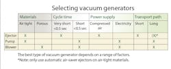
Choosing between an ejector, pump, or blower to produce the vacuum depends on various factors, as shown in the Generator selection table. These include:
• material is porous or air-tight.
• power supply is electricity or compressed-air.
• restrictions on size and weight.
• required cycle times. Use ejectors for short cycle times; pumps or blowers for long distances between the vacuum generator and the suction pads.
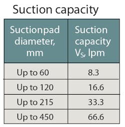
Our example requires short gripping and release times, so vacuum should be generated with an ejector, particularly because the workpiece material is air-tight. First, the vacuum generator size is calculated. The values in the Suction Capacity Table give general ranges, but a more-precise number for 95-mm suction pads is 15 lpm. The recommended suction capacity is for a single suction pad and valid only for smooth, air-tight surfaces. For porous surfaces, experts recommend conducting a suitable test before selecting the vacuum generator.
Calculate required suction capacity V (in m3/hr or lpm) based on:
V = n × VS
where n = number of suction pads and
VS = required suction capacity for a single suction pad. Thus,
V = 6 × 15 = 90 lpm.
In this case, a good choice is a SCP compact ejector with a suction capacity of 116 lpm.
Solenoid valves
Solenoid valves are only needed if a compact ejector does not have integrated valves. In a complete vacuum circuit, solenoid valves control the “grip” (vacuum on) and “release” (vacuum off) functions. They are normally used in vacuum circuits where a pump or blower generates the vacuum. Selection criteria for solenoid valves include:
• suction capacity of the vacuum generator.
• available control voltage.
• operating mode of the solenoid valve (NO or NC).
Nominal flow rate of the solenoid valve must always equal or exceed the vacuum generator’s suction capacity. In this case, the solenoid valve should have a nominal flow rate ≥ 116 lpm. However, because the SCP 20 compact ejector (selected in the previous step) has integrated valves), no separate valves are needed in this example.
Switches and manometers
Vacuum switches and manometers are normally selected based on application requirements and switching frequency. Available functions include:
• adjustable switching point.
• fixed or adjustable hysteresis.
• digital or analog output.
• status LED.
• display with input keypad.
• threaded, flange, or plug-in tube vacuum connection.
• supply-voltage and signal connections via cable or screw-in connectors.
Evacuation times
Finally, we need to ensure that the system, as designed, meets the required pick-up time of < 1 sec. First, determine the total volume to be evacuated VG, which is the sum of the volumes of all the components. This includes:
Suction pads: 6 x 32 = 192 cm3.
Mounting elements: 6 × 9.5 = 57 cm3.
Vacuum hoses: 6 × 43 = 258 cm3.
Distributor volume: 1 × 38.5 = 38.5 cm3.
Total volume, VG = 545.5 cm3, or 0.000546 m3.
Also, don’t forget volumes of any filters or solenoid valves that may be used in a system.
Knowing the total volume, we can calculate the evacuation time, t, from:
t = [VG × ln (Pa/Pe ) × 1.3]/V
where ln = natural logarithm;
Pa = initial absolute pressure (1013 mbar);
Pe = final absolute pressure, (mbar); and
V = suction capacity of the vacuum generator (m3/hr).
For a vacuum generator producing a 60% vacuum, Pe is about 400 mbar absolute. Therefore:
t = [0.000546 × ln(1013/400] × 1.3)/6.95, or
t = 0.0000949 hr = 0.34 sec.
Results show the system as constructed falls well within the application specifications.
The vacuum components selected should make for a well-designed system that operates reliably. However, even if you are confident that the results of the system-design are correct, experts still recommend carrying out tests with original workpieces, to be on the safe side. Nonetheless, the theoretical system design gives a good idea of the general parameters for the intended application.
Markus Schmider is Product Manager and Applications Engineer at Schmalz Inc., Raleigh, N. C. For more information, call (919) 713-0880, or visit www.schmalz.com.
About the Author

Leaders relevant to this article:
