As compressed air does, vacuum puts the atmosphere to work. In a compressed air system, increased air pressure creates the work force. In a vacuum system, air pressure is reduced to a level lower than atmospheric pressure; then the higher pressure in the surrounding atmosphere creates the work force.
Pressure is reduced by evacuating a portion of the air from a closed volume. Doing so produces a pressure differential. In a sense, the volume available to molecules has increased. And the laws of physics state that when volume increases, pressure decreases.
In an industrial vacuum system, the closed container can be a work device, valve, or actuator. A vacuum pump removes air from the system to create a pressure differential.
Mechanical Vacuum Pumps
The two different types of vacuum pumps are commonly used for automation (pick-and-place applications): positive-displacement mechanical pumps and compressed air-powered vacuum generators (also known as Venturi pumps or ejector pumps).
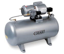
A mechanical vacuum pump may be thought of as a compressor that operates with its intake below atmospheric pressure and the discharge at atmospheric pressure. Compressors and vacuum pumps have identical pumping mechanisms. The vacuum pump is simply piped to withdraw air from a closed container and exhaust to atmosphere, which is just the opposite of what a compressor does.
Mechanical vacuum pumps draw a relatively constant volume of air despite any variation in the vacuum level and can pull a relatively high vacuum. The principle types of mechanical pumps include: reciprocating and rocking piston, rotary vane, diaphragm, lobed rotor, and rotary screw designs.
Although compressors and vacuum pumps have many similarities, two significant differences between compression and vacuum pumping actions must be considered in system design. The maximum change in pressure produced by a vacuum pump is limited; it can never be higher than atmospheric pressure. Plus, as vacuum level increases, the volume of air passing through the pump drops continuously. Therefore, the pump itself finally must absorb virtually all heat generated.
This means temperature is an important consideration when selecting a mechanical vacuum pump because high external or internal heat can greatly affect pump performance and service life. Internal pump temperature is important because as vacuum level increases, less air is present to carry away the heat generated, so the pump must absorb more of the heat.
Vacuum Generators
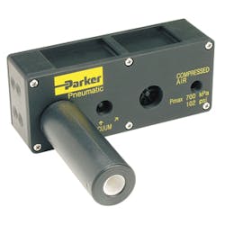
Vacuum generators are powered by pressurized gas, usually compressed air. The compressed air flows into the ejector pump and expands in one or more ejector nozzles. When expanding the stored energy (pressure and heat), it is then converted into kinetic energy. The speed of the compressed air jet increases rapidly, while the pressure and the temperature decrease, attracting more air and thereby creating a vacuum on the suction side.
Two types of vacuum generators are generally used for pick-and-place applications: single, and multi-stage generators. Single-stage unit pumps are compact and emit no heat, but are noisy, provide either high-flow/low-vacuum or low-flow/high-vacuum performance, and consume considerable compressed-air energy in their operation.
Multi-stage generators are much quieter, emit little or no heat, and operate more efficiently than single-stage units. However, multi-stage units cost more than their single-stage counterparts and are not as compact.
Choosing a Vacuum Pump
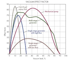
You must consider the vacuum level, vacuum flow, and the ratio between them (pump characteristics) when choosing the correct pump type for a specific application. The effect factor aids in the selection of vacuum pumps. The effect factor is the product of flow (suctioned air quantity) and vacuum level.
The effect factor of several pumps is shown in the illustration. Vacuum level is on the horizontal scale and effect factor on the vertical scale. The plots indicate which type of pump is the most effective at a certain vacuum level. The maximum suction effect is achieved at the highest value of the effect factor. If power consumption is constant, the highest efficiency is reached at the same point.
A vacuum generator has constant power consumption at a constant feed pressure, whereas the power consumption varies with the load for mechanical pumps. For sealed systems, the capacity of the pump is determined by how fast the system can be evacuated to a certain vacuum level. This capacity is called the evacuation time of the pump and is normally specified in standard cubic feet per minute (scfm). This value is multiplied by the volume of the system in order to obtain the evacuation time to achieve the desired vacuum level.
The case is different with non-sealed systems such as lifting a work piece having a porous surface. To maintain the desired vacuum level, the pump must have the capacity to pump away the air leaking in. By establishing the leakage flow, it is possible, by reading the pump data, to find the right pump for a specific application.
If the leakage occurs through a known aperture, the flow can be established. When the leakage occurs through a porous material or in an unknown way, the flow can be established by a test with a vacuum pump. The pump is connected to the system and the obtained vacuum level is read.
Vacuum Cups
Vacuum (suction) cups can lift, move, and hold objects from just a few ounces to several hundred pounds. A vacuum cup adheres to a surface because the surrounding atmospheric pressure is higher than the pressure between the vacuum cup and work piece surface. The cup is connected to a vacuum pump through hose or tubing to create the low pressure. The lower the pressure (higher the vacuum), the greater the force on the suction cup.
The required lifting force is the critical consideration when sizing a suction cup. To determine the right size, use the simple equation for force: F = P × A.
Because the weight of the object being handled is often known, and the diameter (area) of the suction cup is required, a simplified equation for rough estimates can be used. Consideration should also be given to the safety factor (often two) and the number of suction cups.
D = 1.64 (m × n)1/2/ (U × s)1/2
where D = diameter of suction cup, in.
m = mass, lb,
n = safety factor, and
U = vacuum, in. Hg, and
s = number of suction cups.
High levels of vacuum for vacuum cups should be avoided. A deep vacuum means that the pump must work more, and wear on the suction cup increases accordingly. For example, increasing the vacuum level from 18 in. Hg to 27 in. Hg, the force increases by 1.5. However, 10 times as much energy is needed to achieve this 50% increase in lifting force. Therefore, using a lower vacuum level with a larger surface area is generally preferable to using smaller cups at higher vacuum.
Vacuum cups come in a wide variety of sizes, shapes, configurations, and materials of construction, some designed for specific applications. Here, the vacuum circuit is designed for handling semi-porous corrugated cardboard, and the vacuum pad is made of a wear-resistant material with a structure that provides stability in accommodating lateral loads. (Courtesy of Schmalz Inc.)Types of Vacuum Cups
A variety of suction cup types is available that covers virtually all applications. The following are types of cups with brief descriptions:
Universal suction cup—a simple design for handling objects with a flat or slightly curved surface.
Suction cup with short bellows—suitable when level adjustment is required. Several short bellows in one lifting device can handle objects with height differences and varying shapes. The bellows also provides a slight lifting movement that can be used to separate thin items. However, it is poorly suited to vertical lifting.
Suction cup with long bellows—the same applications as for short bellows, but the long bellows can cope with greater differences in levels and provides a longer lifting movement. It is not suitable for deep vacuum and can be equipped with reinforcement rings of polyamide to give extra stability
Deep suction cup—used for curved and irregular surfaces. It can even lift around corners and edges and generally is not suitable for use on flat surfaces.
Flat suction cup with cleats—suitable for flat objects such as cardboard, sheet metal, and porous materials. The cleats stop the object from being deformed from being sucked into the cup. This cup also provides good stability because it produces very little movement.
Flat suction cup with valve—when several cups are connected together in a single system, the system can be disrupted if a suction cup leaks or misses the object to be lifted. To avoid this, each suction cup can be provided with a valve that opens only when the suction cup is pressed against the object. This feature increases safety and reduces air consumption
Suction cup with cellular rubber sealing—suitable for uneven and rough surfaces, such as blocks of stone or concrete and channeled plate. They are available in different shapes and sizes—round, oval, square, long, and narrow—depending on the object to be handled.
Suction cup with minimum movement—particularly suited for thin materials such as paper and plastic film. Inside the sealing strip, the suction cup has an adjustable brace that can be set so that the object is lifted completely flat without risk of deformation. Minimal movement makes these cups suitable for applications requiring accurate positioning.
The material of a suction cup is chosen according to its application with regard to standards of oil resistance, temperature range, durability, and other factors. The most typical materials are silicone, nitrile, and chloroprene. Nitrile provides good durability, plastics have good oil resistance, silicone exhibits resistance to very high and low temperatures, and chloroprene offers high durability but poor oil resistance. Special grades are also available that can meet most requirements.
Fittings, Hose, and Tubing
Fittings often are considered a commodity, but leak-free performance and size are especially important with vacuum applications. The simplest vacuum cup has a plastic fitting so the cup can easily be changed. The fitting is adequate for handling lighter objects that do not give rise to bending stress in the suction cup. However, these fittings are not suitable for applications with high temperatures or oils.
Often a vacuum hose diameter that is too small is chosen in an effort to reduce the volume to be evacuated. The strategy is that less volume to be evacuated equates to quicker evacuation time. What is not taken into consideration in this case is the restriction or limitation of flow that often results. In a typical vacuum application with the right size pump, using ¼ -in. ID hose can make the application slower than using ½ -in. ID hose.
A second factor to consider is the type of hose or tubing being used. It is best to use a product that is vacuum rated. Thin polyurethane tubing should not be used because heat—even room temperature—can cause it to collapse under vacuum, restricting flow. If the application permits the use of tubing, it should be sized so that the vacuum reading is zero when the cups or system is open to atmosphere.
By restricting the vacuum flow through the hose, the entire system is limited. One of the most common problems in system design is improper sizing of the vacuum hose, tubing, or the manifold to which the hose is connected. Unfortunately, the pump is blamed in most cases for system failure, and a larger or different-type pump is installed, resulting in increased costs and energy consumption with no significant improvement in performance.


