Testing an electrohydraulic motion control system
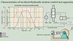
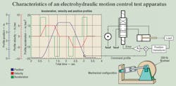
To demonstrate the characteristics of a motion control system, we will examine test results of a valve-controlled cylinder in a closed-loop, positional servomechanism, represented in Figure 1. Otherwise known as a torque cell, the mechanism was designed for special electrohydraulic motion-control training programs. Its cylinder has a 2-in. bore, 1 3/8-in. rod diameter, and 6-in. stroke. The position transducer is magnetostrictive with 0- to 10-V analog output. The amplifier is a conventional servovalve driver amplifier.
Defining the parameters
The load consists of a 4-in. thick, 250-lb flywheel with a 16-in. diameter. The flywheel produces an equivalent mass at the cylinder rod of approximately 1500 lb when the 3.5-in. torque arms are perpendicular to the cylinder rod. The cylinder is connected to the flywheel in a cranking fashion, as shown at the lower-right of the figure. This combination produces a natural frequency of about 20 Hz. Because of the constraints offered by the cranking mechanism, the maximum travel of the cylinder is just under the full 6-in. allowed by the cylinder length.
Cylinder motion is controlled using a PC equipped with a general-purpose data acquisition card with analog input and output. The acceleration, velocity, and position profiles also are shown. An initial dwell (velocity is zero) of 0.6 sec occurs at the beginning of the profile. It is followed by a 0.28-sec period of constant acceleration at 18 in./sec2. Next comes a 0.5-sec period of constant speed at 5.1 in./sec (covering about 2.5 in. of cylinder travel). The end of extension is marked by a 0.28-sec deceleration, followed by a 0.5-sec dwell. The retraction portion of the cycle is symmetrical, however, it terminates with a final dwell of about 0.5 sec.
The motion control profile was synthesized on the PC using the Profile Synthesizer module in the VCCM repertoire of computer programs. No integral or derivative control was used — only proportional.
Three key points
Three important points must be raised:
1. Even though the figure shows three profiles, only the position profile serves as the command.
2. The computer — through a digital-to-analog converter — serves merely as an arbitrary function generator. It holds the data that describes the point-to-point values of the position command profile and provides a “moving target” to stream the profile data to the feedback loop (servo).
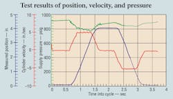
3. The command profile is nothing more than a motion plan, giving the servo something to follow. However, the actual motion of the actuator will simply be a close approximation of the command profile, with the PC serving as a data logger. The PC keeps track of not only where the cylinder should be at every moment, but also where it actually is, its actual velocity, and the instantaneous values of the cylinder pressures.
Command versus output
How closely the cylinder’s actual motion matches the motion command is the subject of this study. The difference between command and feedback is the error signal, which is the numerical difference between the command profile and the feedback signal at every instant in time.
The PC also tracks and saves the error as the profile is fed to the servo mechanism. It should be obvious that the most critical measure of the system performance is the amount of error.
A perfect system would have zero error. In reality, the better the performance, the lower the error. Not so obvious is that the technology exists to allow designing a system to achieve a specific maximum error. This is possible because of a simple algebraic relationship between the following error(the difference between command and feedback when propelling at a constant speed) and the frequency response.
The command profile
The command profile initially was constructed to produce 4 in. of cylinder travel at a maximum steady-state speed of about 5.1 in./sec. The steady-state speed portion of the cycle is that time when velocity is constant — horizontal portions of the red profile in Figure 1.
The entire dwell-extend-dwell-retract-dwell cycle was constructed to run its course in 3.71 sec. This produced a maximum flow requirement of about 4.3 gpm on the cylinder’s cap end during extension — which propelled the load at 5.1 in./sec. This was well within the flow capacity of the pressure-compensated pump, which operated at approximately 1200 rpm. The pump compensator was set to maximum deadhead pressure of 1000 psi. Pump output was supplemented by a 1-gal, nitrogen-charged accumulator to assist in meeting the changing flow demands of the cycling actuator.
A look at the hardware
Plumbing between the pump and servovalve consisted of about 15 ft of SAE 100R2, 3/8-in. ID hydraulic hose rated for 4000 psi and fitted with quick-acting couplings. The 20-gpm servovalve with a pilot designed for 1000 to 1350 psi operation was mounted directly onto the cylinder. Note that the maximum pump supply pressure was just barely within the normal pressure range of the valve’s pilot head. However, this probably had no effect on the results or conclusions that can be drawn. Manufacturer’s data on the servovalve indicate that it had a frequency response of about 50 Hz based on a 90° phase lag.


