Digital resolution with Hall-effect sensors, part 5
Editor's note: This is the fifth installment in a seven-part series on digital resolution and other subjects. Read the rest now: Part 1, Part 2, Part 3, Part 4, Part 6, and Part 7.
An important issue with the magnetic pickup as a speed measuring device is that in its simplest form, it will not work below some threshold minimum speed. The output voltage from the magnetic pickup varies not only in frequency, but also in amplitude. Lenz’s law demands that both vary. At some low speed, the output voltage becomes so low that the digital counter cannot sense the passing pulses. If it can’t detect them, it cannot count them, so data errors will occur. This is the effect that results from the amplitude modulation.
In the case of pump speed, for example, the conditions near zero are normally not very important, so magnetic pickups are viable. But, if zero speed detection is needed, then the magnetic pickup must be replaced with one that can detect the gear teeth right down to zero speed. Such a device is the Hall-effect sensor.
The Hall-effect solution
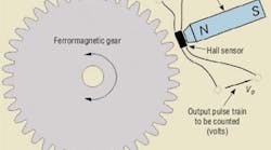
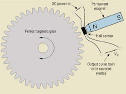
The advantage of the Hall-effect sensor, Figure 1, is that it does not rely upon a changing magnetic field (Lenz’s law) to generate its output voltage. It senses only the amplitude of the magnetic field and generates a proportional output voltage. Thus, the output from the Hall-effect speed sensor varies only in frequency, not amplitude, right down to zero speed.
The Hall-effect sensor is an integrated circuit with wave shaping functions, so the final signal is a square wave of constant maximum and minimum amplitudes, which other signal conditioning circuits can deal with very nicely. The disadvantage of the Hall-effect sensor is that it requires a dc power supply to power its onsensor circuits. However, this is not a serious problem in most applications. When properly configured, this sensor can also serve as a low-resolution shaft encoder if enough ferromagnetic irregularities (teeth) exist at the periphery of the gear.
This speed measurement method relies on a pulse train for its base data source. If very high resolution and speed are needed, and frequency is the parameter of choice, you can use an optical encoder on the shaft. The advantage of optical encoders is that they accommodate thousands of pulses per revolution, giving very high resolution, even with frequency measurement and short gate times. Plus they work down to zero speed, just like Hall-effect sensors. However, optical encoders are the most expensive type.
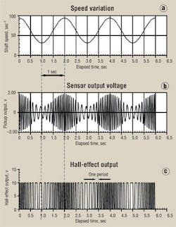
Figure 2 summarizes operation of magnetic speed pickup sensors. Figure 2 does not necessarily represent the conditions for shaft speed, but, rather, some other scenario devised to help illustrate the AM and FM features.
Figure 2a represents the instantaneous speed of a motor shaft. It could be a an unstable feedback control loop that is hunting about the quiescent point. The shaft speed is varying between 32 and 94 radians/sec (or, simply sec-1), with the average being about 63 sec-1. These angular speeds correspond to 305 rpm, 897 rpm, and an average shaft speed of 600 rpm. The average frequency of the pickup output, Figure 2b, is 62.8 sec-1, which means only one pulse occurs per shaft revolution. This is not a typical setup, but it produces graphs that separate the various points that are important in illustrating this speed measurement method. It is a good graph for teaching the principles involved.
There are two important features of Figure 2b. First, as the shaft rotates, the frequency of the output varies, with the highest frequency coinciding with the highest speed and the lowest frequency with the lowest speed. This should not be surprising. But notice that the amplitude of the pickup output also varies. This is consistent with Lenz’s law. The faster the shaft spins, the higher the voltage. This is the characteristic mentioned earlier, where if the speed gets down to some minimum level (not easily determined without testing it), the voltage will be so low that the electronic counter cannot detect it. The counter will return a value of zero speed, even though the shaft may actually be rotating at a finite low speed.
Figure 2c shows the effects of using a Hall-effect speed pickup rather than a simple magnetic type. It does not depend on speed to generate its output voltage. Instead, it generates an output that depends only on the magnitude of the instantaneous magnetic field strength (flux density) in the vicinity of the sensing element. It does not inherently generate a square wave. The squaring shown in Figure 2 is done with shaping circuits that normally accompany the Hall-effect sensor.
At the gate
Note also in Figure 2 that a 1-sec time span has been drawn and placed at an arbitrary point along the graph. It represents the gate in a typical electronic digital counter. The counter opens its input gate for a precise time, for example, 1.000000 sec. While the gate is open, each pulse from the speed pickup adds a count to the counter’s digital register — as in the odometer in your car. At the passage of the precise gate time, the gate closes, and the counter register holds the number of pulses that have passed in 1 sec, which is, by definition, the frequency of the pulse train in cycles/sec, or Hertz.
With the square wave as shown, the detecting circuits can easily sense the large voltage change and reliably measure the total number of pulses. However, the resulting count will result in an evaluation of the average frequency or speed over the gate interval time. It is not instantaneous speed. Imagine that the 1-sec interval now starts at some different time along the graph. The value shown in the electronic counter’s output display will depend on where the one second gate starts and stops.
For example, if the gate were to start at, say, 1.5 sec (Figure 2) and then stop at 2.5 sec, the number of counted pulses would be greater than if the gate started at 2.5 sec and ended at 3.5 sec. (Each time the gate opens, and the counter displays the accumulated count, the displayed value is called a sample.) In normal operation, the gating and displaying (sampling) is repeated at regular or irregular intervals. The displayed value would vary from sample to sample and lead us to conclude that the speed was varying, which it clearly is, or is behaving erratically, which it clearly is not.
Now consider that the gate time has been increased to exactly 2 sec. No matter where the interval is placed, the total number of pulses will be 10, leading us to conclude that the speed is absolutely constant! The graphs clearly show a different scenario. But this is the disadvantage of frequency measuring methods. They produce an average over some stated interval (gate time on the counter), they always produce delays, and they can sometimes be rife with time delay errors when used for data evaluation and speed control purposes.
On the other hand, frequency speed measurement can be useful — for example, during steady-state pump performance testing, where average speed is the desired quantity. But when doing closed-loop control, the averaging error and the subsequent delay can be difficult to deal with.
Figure 2 also shows a smaller time interval, labeled One period, or one complete cycle of the Hall-effect output. It is a measure of the small time interval between the rising edges of two consecutive square pulses. The choice of the particular pair in the figure was completely arbitrary. The average time between two consecutive leading edges in the example is about 100 msec. If we measure the time interval, we can determine the speed more quickly — and if done properly, with greater resolution (more significant digits).
To consider the resolution, return to the 1-sec interval. During the gate interval, 10 pulses (Figure 2) will have been accumulated, and the register will read 10 Hz. This is only two significant digits. To combat this poor resolution, it is common to increase the gate time to, say, 100 sec, which will produce a count of 1000, or four significant digits. This improves the resolution, but the cost is an increased delay time and speed averaging over a much longer interval. It depends on the application, but both results are very likely to be very objectionable. If the period is measured, we can improve the resolution at the same time the time delay is reduced.
The Hall-effect solution
Many digital electronic devices (computers, for example) are equipped with an internal clock, which is just a very high frequency electronic oscillator. A common value in electronic counters is 1 MHz. In the normal counter function, an internal counter starts at the occurrence of an arbitrarily timed “trigger,” The trigger also opens the gate to allow the unknown signal pulses to enter the counter register. Meanwhile, the internal counter is adding up internal clock pulses until it counts one million pulses, at which time it shuts the gate off. In this manner, a precisely determined 1-sec gate occurs with a resolution of one PPM.
When measuring the period of a changing signal, the roles of the unknown incoming signal and the internal clock are reversed. That is, the first edge of an incoming pulse opens a gate. The gate allows pulses to pass from the clock to the counter register, so the register is accumulating microseconds (one million clock pulses per second). When the leading edge of the next unknown incoming pulse arrives, it shuts the gate off. So now, the contents of the register is the number of μsec between two consecutive leading edges.
The result is a measurement much more closely related to the instantaneous speed and has been acquired in a much shorter time. The general rule is to measure frequency when the frequency is high, but measure period when the frequency is low. In digital systems with processor control, it is a relatively simple task to make a method switch on the fly. It is possible to develop very simple formulas that will determine when the method switch should take place in order to maintain the best possible resolution for a given measurement situation.
|
Basic Electronics for Hydraulic Motion Control This textbook is written specifically by a practitioner of the hydraulic art for engineers and technicians working in hydraulics. It is filled with analogies to simplify the understanding of concepts: transducers, interfaces, signal conditioners, pulse width modulation, controllers, amplifiers, transistors, analog electronics, digital electronics, and much, much more. It is a must read and reference for anyone interested in certification in the exploding technology of electrohydraulics. Authored by Jack L. Johnson, P.E. and edited by Hydraulics & Pneumatics, the hard cover textbook (ISBN 0-932905-07-2) contains 438 pages and sells for $99.00, plus shipping and sales tax. To order, or for more information, visit the Bookstore and download the order form. |


