Physics of motion control and flow profiles
The machinery of industry is being-required to operate faster, with shorter cycle times and higher reliability — all over a longer lifespan. At the same time, products are required to be cheaper and consistently of higher quality. Machinery must be free of shock, vibration and noise. Competitive pressures are forcing the issue.
In some respects, the many requirements are at cross purposes. For example, faster operating speeds and shorter cycle times are accompanied by higher acceleration, which can create higher stresses and more noise. Hydraulic machinery, of course, can be made that meets all the requirements listed above. However, to do so certainly requires high versatility, power, and low cost of electronic controls.
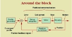
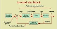
A system that meets all the performance requirements above is a motion control system. A simplified block diagram of an electrohydraulic motion control system is shown in the illustration. The positional servomechanism is vital to the modern motion control system. It receives a command, or input voltage, and the actuator moves to a position where the position feedback voltage equals the command. Once this happens, zero error occurs, which shuts the system down. The actuator will have acquired the target position, provided the command voltage was the correct value that corresponded to the target position.
Therefore, for the motion of the actuator to move with acceleration, speed, and acquire the position demanded, we need only send a command profile that corresponds to the required acceleration, speed, and position. The servo will do our bidding — if the servo loop is fast enough.
Profiles in command
The command profile is generated electronically by a command profile generator. It could be a general-purpose computer with output from a digital-to-analog (D/A) converter that sends the profile to the servo input. The procedure usually involves generating the digitized profile ahead of time, which is stored as a data array table in computer memory. A simple program streams the data array out to the D/A converter, which converts the digits to a proportional analog voltage. Of course, the servo system can react to that analog signal and will try to follow it.
The command profile generator could also be a PLC with a D/A converter, or one of many commercially packaged, industrially hardened motion controllers. All of these devices are digital in their architecture and are actually specialpurpose computers. The most significant difference between them and a general-purpose computer is the method of programming. However, programming PLCs and motion controllers is beyond the scope of this discussion.
The profile generator can be implemented by purely analog means as well. The circuits would include a ramp generator and possibly some smoothing filters to bring the acceleration under some degree of control. The analog profile generator requires adjustment, or tuning, which can be difficult. Furthermore, adjustments may drift over time. On the other hand, the tuning an analog profile generator is done on-line, in real time, so that the effects can be observed as they are taking place. Because setup of the digital system is done ahead of time, some level of abstraction always exists in the selection of the desired values and getting them into the system.
A disadvantage of the analog system is its tendency to drift, or change characteristics with time. It has to be "retweaked" periodically. Digital systems, barring a hardware failure, are extremely repeatable. This is because performance is controlled by software — which cannot wear out, no matter how often it is cycled — and by the computer's clock, which is exceedingly stable.
Which ever method of profile generation is chosen — and the choice may hinge upon personal preferences or biases — the aim is the same: The profile is the carrot on a string that "leads the actuator by the nose" in order to affect the desired motion in the actuator.
The effective implementation of motion control has two important steps:
- Design a profile that contains the accelerations, speeds, and positions that will achieve the required machine cycle.
- Design the electrohydraulic positional servomechanism with a bandwidth high enough to follow the command profile within the allowable following and positioning errors.
When so designed, the machine will be smooth, quiet, reliable, repeatable, and generally wellbehaved.
Jack L. Johnson, P. E., is an electrohydraulic specialist, fluid power engineering consultant, and president of IDAS Engineering, East Troy, Wis., Contact him by calling (262) 642-7021 or via e-mail at [email protected]


