Hydraulic-Electric Analogies, Part 3: The Open and Closed Contradiction
This file type includes high-resolution graphics and schematics when applicable.
An open electrical switch blocks current, whereas a closed switch conducts. A closed hydraulic valve blocks flow, but an open valve allows flow. These are clearly contradictory analogies that are often confounding to those who are seeking to cross-fertilize, so to speak, and learn the other language and concepts. There is a method to this madness, or at least an explanation, that belongs in the pantheon of “No wonder we don’t understand each other.”
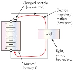
The open-closed explanation requires at a least rudimentary understanding of both electrical and hydraulic circuit diagrams. Figure 6 shows a battery symbol inside the envelope labeled Multicell battery. The battery symbol itself consists of alternating short and long horizontal lines centered along a vertical line. Nominally speaking, the number of short-long pairs indicates the number of cells in the battery. However, no hard-and-fast rule exists for this matter. As shown, and with that interpretation, our battery would have six cells. If each cell produced, say, 2 V, this would be a 12-V battery because all the cells are connected in series. It could be a typical lead-acid automotive battery, or it could be some dry cells such as the familiar AA size that have become commonplace in most portable electronic devices. Many characteristics are not conveyed in the battery symbol. For example, unless we know the value for E, we don’t know the battery voltage. Also, the rectangular envelope is not part of the battery symbol. It was included for clarifying the boundaries of the battery.
The battery supplies power for the circuit. Its voltage gradient motivates any of the loosely bound conductors’ electrons to move away from the negative terminal and head toward the positive terminal. The electrons are charged particles — that is, they hold an electrical charge. As electrons move through the circuit, their motion, collectively, is called electrical current. Electrical charges in motion constitute electrical current. Quantification of current is made with the international standard called the ampere. The ampere is the average motion of 6.241 × 1,018 electrons (1 coulomb) in 1 sec. We cannot count such a number, so other means are used for standardizing the international unit of the ampere.
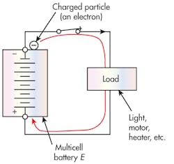
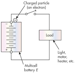
Figures 7 and 8 are similar to Figure 6, but they have a switch added to the circuit. The switch in Figure 7 is in the closed position. This means it will conduct, so electrical current will exist through the circuit to the load. Figure 8, however, shows the switch in its open position. The source of the confusion comes from the fact that a complete path must exist for electrical current to exist. All electrical circuits must close on themselves so that electrons can travel around the circuit in a never-ending way. We say that the circuit is closed. Only then will there be a current.
The continuous current path has been broken in Figure 8 because of the state of the switch. We say that the circuit is open, and there can be no current. So, the terms “open” and “closed” are really circuit references, not switch references. However, in the sloppiness that sometimes crowds out common sense in the jargon, we have applied circuit terms to the switch. Thus, an open switch blocks while a closed switch conducts. The terms continue to be applied in the electrical world and are even accepted as perfectly normal and correct. But to those folks who are arriving from a hydraulic background, it can be confusing. Don’t try to fight it. It’s ingrained in the language.
Polarity and current
Referring back to the basic circuit, we know from the battery symbol that the negative terminal is the upper one, conveyed in two ways. First, there is a minus sign at the upper terminal and a plus sign at the bottom. Second, it is standard convention that the short horizontal line always identifies the negative side, and the long line is the positive side of any battery symbol. The negative terminal is called the cathode and the positive terminal the anode. These are universal terms that apply to anything requiring or producing voltage of a specified polarity, either plus or minus.
The battery is connected to a load through external wiring. If this is your car, the load represents every electrical device inside your car. It includes lights, radio, motors, rear-window defogger, and so on. From a concept point of view, though, the external circuitry provides a completed path for electrical charges to travel around the circuit.
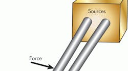
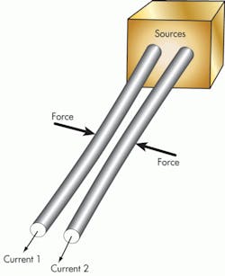
Charged electrical particles in motion produce a magnetic field that surrounds the space around the conductor carrying the current. For example, if current exists in only one direction, it will affect a compass placed in the vicinity of the conductor. In addition, a force of attraction exists between two current-carrying conductors in close proximity to each other, Figure 9. That force can be measured to determine when a standard ampere exists in the conductors. The calibration must be done in a vacuum, and relative distances must be standardized and known, but it avoids the tedium of counting electrons. More importantly, the procedure relies on the conventional and internationally standardized physical quantities of force and length.
No hydraulic fields
The hydraulic analogy to electrical current is hydraulic flow — electrical current is the movement of electrons, whereas hydraulic current is the movement of fluid molecules. Flowmeters are mostly mechanical devices that can be calibrated with mechanical-calibration equipment. They rely on either a weight or volume of fluid accumulated over a period of time.
Two profound differences exist between hydraulic and electrical circuits. First, electrostatic force causes electrons to be attracted to protons. That force accounts for the motivation for the electrons to move from the battery’s negative terminal to the positive terminal through external circuitry. The force also arises when charges are separated and account for the shocks we often get after walking across a carpet, where an electrostatic force causes tiny bolts of lightning. If a body accumulates excess electrons, then other bodies are devoid of them, and a force of attraction exists between them. When charges are isolated, they create an electric field around them that permeates their immediate space. In other words, the existence of isolated charges can be detected even when they cannot be seen because they alter their environment — that alteration being the electric field. It is not a magnetic field, it is the electric field, sometimes called an electrostatic field.
If we isolate a molecule or any volume of fluid, it is not significantly attracted to any other volume of fluid. The isolated fluid volume does not alter the space around it with any kind of field that we can detect without physically contacting it or seeing it. The electrostatic field is not particularly important in fluid power.
Second, electrons create a magnetic field merely because they are moving. That field can be detected by an instrument that measures magnetic fields. The space surrounding the moving particles is altered. When the electron movement stops, the field disappears. In contrast, if fluid molecules are in motion, there is no change to the surrounding space. To detect the fluid motion, the circuit must be penetrated, and a flowmeter must be inserted to accept the incoming fluid and discharge it while measuring its rate of passage. To be sure, the measurement of electrical current can be done by breaking the circuit and inserting an ammeter.
So, electrical charges create electric fields merely because of their presence and magnetic fields when they are moving. They exist and they are important because they make all of our electronic devices possible. They account for radio and all the wireless things in our world. Magnetism is put to use in solenoids and the magnetic pickups in flowmeters and speed sensors. It is, indeed, an important phenomenon for practitioners of fluid power.
A summary to this point
We’ve explored some basic concepts regarding similarities and differences between the electrical and hydraulic technologies. Fluid flow and electrical current are analogous because they involve particles moving around a circuit. Fluid flow is measured in in.3/sec, gpm, or lpm. Current is measured only in amperes or fractions thereof, such as mA or µA, etc. They are both measures of particle-movement rates.
Pressure and voltage represent potential for motion, not motion itself. They simply exist at some arbitrary points in their respective circuits. They are the motivational quantities that spur their respective particles to move from a point of high potential to a point of lower potential. The pressure-voltage analogy breaks down because there is no such thing as absolute zero voltage, but there is a condition where there is zero pressure, ideal though it may be. The result is that hydraulic circuits can cavitate because the pressure can only reach absolute zero. Electrical circuits, on the other hand, can never cavitate. Voltages can go as far negative as is necessary to satisfy the physical laws of electrical technology.
Furthermore, electrons can create electric fields around the conductors containing them, and moving electrons generate magnetic fields around their conductors. Hydraulic fluid, however, has no such effect on the environment surrounding it conductors.
The open-closed contradiction arises because the electrical language applies a circuit condition to a switch. That is, we open a switch in order to create an open circuit, which is one that can conduct no current.
