Today’s Versatile Transducers Step Up Performance
We all know the roles of mechanical pressure gauges and switches. They either give us a visual indication of hydraulic pressure, or open or close a switch when reaching a certain threshold pressure. Electronic pressure transducers do the same, but more effectively and with a single component instead of two or three. Furthermore, an electronic pressure transducer provides more output variations, longer life, and greater accuracy.
This file type includes high resolution graphics and schematics when applicable.
A transducer converts a physical parameter into an electrical signal or vice versa. The sensing element at the heart of a transducer sensor is, in fact, a type of transducer. Different technologies are used to convert pressure into an electrical signal. Most pressure transducers rely on the physical deformation of some kind of diaphragm to create a change in an electrical output signal. The transduction from physical deformation to electrical signal is often produced by strain gauges, which exhibit a change in electrical resistance proportional to physical deformation.
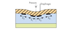
A type of strain gauge commonly found in pressure sensors uses piezoresistive technology, which is based on changes in the electrical resistance of a deforming silicon semiconductor. A stainless-steel housing protects the silicon chip; fluid pressure is indirectly transferred to the diaphragm through a liquid medium, usually silicon oil (Fig. 1). In this technology, temperature-related effects must be considered due to the transfer fluid’s properties. This type of measurement is typically applied in systems with high dynamic pressures.
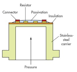
Thin-film technology uses a sensing element mated to a stainless-steel carrier (Fig. 2). Resistors and other circuitry are placed on the diaphragm, and measurement is based on output from strain gauges. The advantage of stainless-steel thin film is its ability to withstand the high peak and burst pressures often encountered in hydraulic systems.
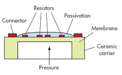
Thick-film technology also uses strain gauges, but in this case there’s a ceramic carrier (Fig. 3). The resistors and other associated circuitry are placed on a diaphragm using a thick-film process. Ceramic cells offer long-term stability and good corrosion resistance.
In capacitive measuring cells, one electrode is fitted to an elastic membrane while the other is on the fixed support or housing surface located on the opposite side (Fig. 4). This forms a variable capacitor, which means that one electrode follows the movement of the membrane. As the pressure increases or decreases, the distance between the electrodes changes, causing a change in capacitance that’s detected by electronic circuits.
Transducer output
Today’s electronic pressure sensors incorporate output switching functionality as well as visual display of the current pressure. Because these devices are electronic, many output characteristics are available as opposed to the simple on-off functionality of the classic mechanical pressure switch. These include multiple discrete outputs from one sensor with programmable functionality.
In many cases, a sensor will provide a single discrete setpoint output and a continuous analog output proportional to the pressure value. The discrete output can provide an alarm function, whereas the analog output delivers a continuous output signal.
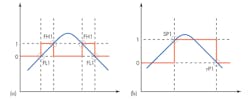
Discrete outputs can be programmed for the application at hand. The most important is the pressure span between the on and off setpoints, sometimes referred to as hysteresis (Figs. 5a and 5b). The turn-on pressure occurs at SP1 and turn-off (reset) occurs at rP1. The advantage of digital technology is that these programmed values can be very close together for tight pressure control, as long as they are located within the sensor's normal measuring range. Hysteresis keeps the switching outputs stable even if the system pressure fluctuates around the setpoint.
Operating pressure range
Several system operating parameters must be considered when selecting a pressure transducer. First is the system’s nominal operating pressure. For the best combination of reliability and sensing resolution, a pressure transducer should have a nominal operating pressure between 50 to 60% of its maximum pressure rating.
However, pressure ripple, cyclical pressure changes inherent to the pump’s design, can cause problems with the transducer’s mechanics as well as the logic of the electrical controls. Even though a pump maintains a reliable average output pressure, pump ripple results from peak low and high pressures of the pump’s output.
Electronic transducers offered today can delay the switching output, which is beneficial if the system exhibits pump pressure ripple. Providing a certain amount of output delay can help alleviate unnecessary output switching due to false pressure changes from the pump. Delays can be programmed up to 50 seconds or more, but usually are much shorter to compensate for pressure ripple.
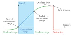
Overload pressure is another common issue with hydraulic systems (Fig. 6). Overload pressure results from valves suddenly opening or closing, or by pump cavitation. These pressures may exceed the transducer’s specified range without causing permanent damage or any change in accuracy. If they approach burst pressure, though, they can cause permanent damage to the sensing accuracy or even mechanical damage to the sensor.
Pressure spikes
Pressure spikes are sudden increases in pressure that can exceed 10 times the maximum of the measured pressure range (Fig. 7). The duration of these pressure peaks is typically very short—only milliseconds—and may be caused by valve switching, cavitation, or sudden load changes (such as running a hydraulic cylinder at speed into a hard stop). Any of several methods, such as accumulators or surge tanks, protect the overall system from these peaks.
If transducer damage from pressure spikes is a concern, then a pressure snubber can be installed inline with the pressure sensor. A snubber is a fitting installed between the fluid connection and the transducer. It has a mesh filter that allows fluid to pass through, though not in large volumes in order to protect the sensor.
Accuracy and temperature
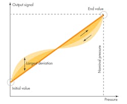
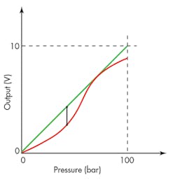
The term accuracy generally refers to how a transducer’s actual pressure-response curve deviates from an ideal pressure-response curve (Fig. 8). Usually it consists of the combined effects of nonlinearity, hysteresis, and repeatability expressed as a percentage of deviation from ideal values. Typically, these values are applied over an instrument’s full-scale output (FSO) (Fig. 9). They’re based on either an ideal straight line or an adapted straight line, commonly given as best fit straight line (BFSL). Accuracy often is specified as a percentage, for example ±0.5% FSO BFSL.
Temperatures extremes can cause transducer output to change. Temperature drift is a shift of the switching point caused by a change in ambient temperature. Methods vary from one manufacturer to another, making it difficult to draw direct comparisons. In some cases, only typical values are specified. In others, the value is a percentage of the FSO per 10°K; for example, ≤±0.3% FSO/10°K.
Today’s electronic pressure transducers are expected to provide tighter control than the mechanical gauges and switches they replace. Furthermore, digital displays make even small fluctuations in pressure more noticeable. And although pressure transducers don’t require the periodic maintenance of their mechanical counterparts, they may need recalibration after being subjected to extreme pressures or temperatures.
Another key point is that mechanical pressure gauges and switches have a finite life. Meanwhile, though electronic transducers may also have a finite life expectancy, their lifetime is specified in hundreds of millions of cycles and will maintain a much greater accuracy over that extended lifespan.
Transducer output
Today's pressure transducer displays are multifunctional. Not only do they provide dynamic measurements, they can also be used to program or configure output. Displays options include pressure, parameters, parameter values, scaling of the device, and output status, as well as programming keys and in some cases keypad lock-out functionality to prevent unauthorized tampering. Some manufacturers require a tool to program the sensor; however, more advanced manufactures comply with VDMA standards that don’t require a tool.
Some applications must be able to lock out the transducer’s programmable features. Most manufacturers require a user to hold down two buttons for a set time to lock the display. If the need arises for process changes, then the same procedure of holding down the buttons for a period of time is used to unlock the display. A more progressive solution uses a four-digit password to truly lock the display with a unique code.
Pressure transducers that offer both discrete digital and analog outputs with a built-in display offer the ultimate in convenience, especially compared to past solutions with as many as three components. If the application requires only an analog feedback without display, or the display will not fit due to mounting and space limitations, then a simple pressure transmitter may be the better choice.
Pressure transmitters typically don't incorporate a display, and usually have either a 0- to 10-V dc or 4- to 20-mA output. Their compact size suits them for space-restricted areas—the devices consist of only a fluid pressure connection and an electrical connection. The sensor is selected for the pressure requirements, and the analog output operates across that entire range. For instance, a 0- to 145-psi pressure range would output 0 to 10 V. Current-output versions (4 to 20 mA) are more commonly used in industrial applications because wiring lengths can be longer and, unlike voltage outputs, aren’t affected by electrical noise.
Making a wish list
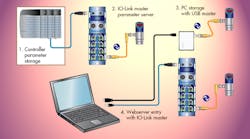
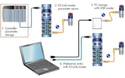
The ultimate pressure sensor would have all of the capabilities mentioned so far, as well as provide enhanced functionality and parameterization. Pressure sensors connected to factory networks through sensor-level communications protocols, such as IO-Link, can improve process flexibility and control through enhanced sensor monitoring, configuration, and error reporting back through the system controller (Fig. 10). Digital transmission of analog values over low-cost, unshielded three-wire cabling ensures high signal quality over longer distances, and eliminates signal delays and distortions that can plague analog interfaces.
Networkable sensors reduce downtime and configuration errors with plug-and-play functionality. Maximum system flexibility can be achieved during operation, thanks to quick and remote modification of parameters through the control system rather than at the physical sensor itself. In addition, process diagnostics, data, and errors can be reported directly to the controller and displayed on man-machine interfaces.
Jack Moermond is Marketing Manager, Object Detection Sensors, at Balluff Inc., Florence, Ky. For more information, call (859) 727-2200, or visit www.balluff.com.
This file type includes high resolution graphics and schematics when applicable.
