Questions Answered on Electrohydraulic Control
Download this article as a .PDF
Jack Johnson has spent his entire career dealing with the issues of electrohydraulic control systems, involving both the design of equipment and teaching the underlying principles at the Milwaukee School of Engineering and educator at seminars. He also served as the director of the Fluid Power Institute at the Milwaukee School of Engineering. Presented here is a small collection of questions that recur through the years, along with answers. For more information, contact him via e-mail.
Q: I’m confused about servo and proportional valves because the differences don’t seem clear-cut. What, exactly, is the difference between a servovalve and a proportional valve?
A: The generic descriptive term that applies to this class of valves is, “continuously variable, electrically modulated, hydraulic directional control valves.” Germans use the term stetigventil—a continuously differentiable valve, and servovalves and proportional valves fall within this generic valve type. Unfortunately, we have no single word in English to cover these valves. The generic term should be “proportional valve,” with two subcategories: servovalves and proportional valves.
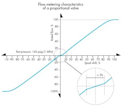
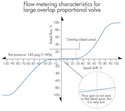
An extensive research project at the Fluid Power Institute was conducted to determine how a user could distinguish between a proportional valve and a servovalve. We used electronic enhancements to determine the extent to which a proportional valve could be made to perform like a servovalve. Performance characteristics and construction and manufacturing methods were examined. The most significant discriminator was the amount of center overlap. We eventually defined a servovalve as one with less than 3% of center overlap, whereas a proportional valve has center overlap of 3% or more.
Q: What is a valve overlap?
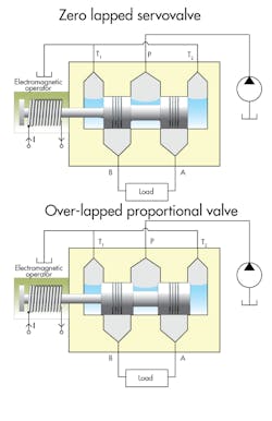
A: Valve lap, or valve overlap, refers to the amount of spool travel from the center position required to start opening between the powered input port and the work (output) port or the tank port. A zero lapped valve is one in which any tiny, differentially small amount of spool shift, either way, starts the opening. However, there is no contact between the OD of the spool and ID of the bore. And even zero lapped valves have some slight amount of overlap. Nonetheless, the zero-lapped term persists.
Q: Why is valve overlap the single most important discriminator between servo and proportional valves?
A: Simply put, the MSOE study designated servovalves as having near-zero overlap and proportional valves as having significant overlap. Therefore, a so-called zero-lapped valve can be given servovalve status and still accommodate normal manufacturing tolerances because it allows up to 3% overlap. Furthermore, you can rarely distinguish any system performance degradation caused by that slight amount of overlap. In fact, some amount of overlap is desirable because it reduces the amount of spool-to-bore leakage.
Whenever performance specifications contain requirements of a specific accuracy, a servovalve is probably going to be required. For example, a user may have a requirement that a cylinder must have total travel of 24 in. while propelling a 10,000-lb. load at a speed of 15 in./sec, and must achieve a final position with an error not to exceed 0.020 in. This kind of performance specification begs for a servovalve and motion control design methodology.
The most accurate systems are called null seeking. This means that when the controlled output—say, the position of a cylinder—is in the desired position, the valve spool is near its center position. To achieve great accuracy in positioning, any small disturbance of the cylinder’s position (caused, for example, by a change in external load) must be immediately counteracted by a commensurately small move in the spool to overcome the disturbance. Such null-seeking operation is also required in many pressure control systems.
Zero lap in the valve means it can react and do its correcting job regardless of the direction of the disturbance and no matter how small it may be. Again, the term zero-lapped is an idealized term; the real valve will likely have a slight amount of overlap.
Q: What is valve null?
A: Valve null is a specific point of a servovalve’s pressure metering curve where the two deadhead (blocked port) work port pressures are equal. Servovalves are equipped with a mechanical adjusting device so that with no electrical power applied (connector disconnected from the valve), a spring or magnetic force can be changed to make the two work port pressures equal. That is normally where the factory adjusts a valve during final test, assuming it will be used on an equal area cylinder.
If the application has an unequal area cylinder, the user removes the valve connector (which will probably cause the piston to creep), and changes the null adjustment until the cylinder stops moving. Of course, with the cylinder stopped, this will result in unequal pressures in the cylinder due to the piston area differences and affected by any non-zero load.
Q: What is null shift in a valve?
A: Null shift is an effect that causes the valve to drift from its null point. For example, if a valve is nulled, and the temperature or supply pressure changes, the valve will no longer be at its null point. Either the current or the mechanical null screw will have to be adjusted in order to re-acquire the precise null point. The important issue to remember is that anything that causes the null of the valve to shift results in an error in the closed-loop system, such as a positional servomechanism or a pressure control system. Null shift is important only in zero-lapped valves.
Q: I am trying to decide which type of valve to use in my closed-loop application, a servovalve or a proportional valve. I am impressed with the performance of a servovalve, but I am concerned about its high pressure drop. How do I decide between the two?
A: The pressure drop across the valve is a source of confusion at worst and misconception at best. All servovalves are flow rated at 1,000 psi (7 MPa according to ISO 10770-1, which converts to about 1,015 psi) and have been for several decades. The rated flow of a servovalve is measured with 1,000 psi differential pressure from the pressure port to the tank port while the work ports are looped. On the other hand, proportional valves are flow rated at 145 psi (1 MPa in ISO 10770-1).
This difference in flow rating pressures leads the uninitiated to conclude that proportional valves have lower pressure drop. This is simply false. When sizing the valve, the sizing process calculates the required valve flow coefficient, that is, the KV value. It makes absolutely no difference which valve type you are planning to use; the properly sized proportional valve has exactly the same KV value as the properly sized servovalve. They will have the same-sized flow area and the same pressure loss in the application. There is absolutely no pressure drop advantage of one over the other.
The two valves don’t have different flow ratings because they have different amounts of opening, but because their flows are rated at different pressures. The refusal of the industry to adopt publication of their valve KV values proliferates the confusion.
Q: Why do so many proportional valves have lower hysteresis than servovalves do? Aren’t servovalves supposed to be more “precise?”
A: Hysteresis is the property of some input-output devices, such as valves, sensors, magnetic devices, mechanical linkages, and such that causes the characteristics with increasing input not to track the same path as with decreasing input. The two common mechanical causes of hysteresis are static friction and backlash, and there is also magnetic hysteresis.
Electrohydraulic valve hysteresis is caused by all three effects and is, therefore, an important performance parameter. Hysteresis causes errors in the servo system because it essentially creates a null shift in the valve, depending on the direction from which the targeted output, say position or pressure, is approached. Hysteresis is undesirable in valves, but inevitable.
As for the issue with “cheap old proportional valves” having lower hysteresis, that is often true. The reason is that many servovalves use a feedback wire or spring to achieve proportioning of spool position. This is purely mechanical linking between the torque motor and the main spool. Mechanical and magnetic hysteresis effects will occur, and a typical figure in manufacturer’s literature may list hysteresis as less than 2%.
Many proportional valves use an LVDT spool position sensor with electronic feedback, and the result is a “tighter” spool position control loop and lower hysteresis. Some multistage servovalves use LVDT spool position control. They, too, will have lower hysteresis, and a common published value is less than 0.5%. It takes extra special test techniques to find the true amount of hysteresis in such valves, because it is so small. When the valve threshold is low enough, any resulting limit cycling with PID (proportional integral derivative) control is likewise low enough to be unnoticeable.
Q: I have heard that proportional valves have better contamination tolerance than servovalves, and that some designs are better “dirt eaters” than others. What is your assessment of these claims?
A: I, too, have heard these same claims, but I remain skeptical. The arguments that I have heard usually focus on a single feature of a given design and make the claim that because that feature is better at rejecting contaminants, the whole valve is, therefore, better. For example, the advocates of direct-acting valves make the claim that “there are no tiny nozzles to plug up.” This argument is specious at best, because the nozzles (flapper-nozzle design), being greater than 0.002 in. (50 µm) in diameter, require gigantic contamination particles to do the plugging up. I maintain that any system that is circulating 50-µm particles has many more serious problems, not just with the servo or proportional valves.
The fact is that contaminants affect valves in other ways. If contaminants are abrasive, they will erode surfaces and metering edges. With modern machining methods, servo and proportional valves have the same spool-to-bore clearances, and a piece of hard contaminant can create spool lock up in any type of valve.
This subject is very important, and other people have much more expertise than I. But I see one basic problem with the claims of the advocates: There is no internationally standardized, objective test method for determining the contamination tolerance of valves. Attempts to develop such standards have met with failure from lack of resolve at the international level. Until that standard emerges, I remain skeptical, and users are at the mercy of their suppliers and their own wits to keep them out of trouble. And it remains absolutely true that clean fluid is everybody’s friend. Follow proper cleanliness procedures so that the filters become your dirt eaters in the system—and maintain that cleanliness level.
Q: What is PWM?
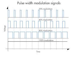
A: PWM stands for pulse width modulation. It is an on-off method of controlling output current and voltage (power). The output stage of the PWM amplifier is a transistor on-off switch. Proportional control is achieved by controlling the amount of on time to off time. The rate at which the switch turns on and off, called the PWM frequency, is normally fixed (from 30 or so Hz to as much as 40 kHz—electronic circuit designer’s choice), and well above the frequency at which the hydromechanical system can respond. The valve and actuator, then, respond to the average current, not the instantaneous current.
For example, suppose the PWM frequency of a certain PWM valve driver is, say, 100Hz. The period, then, is 0.010 sec; that is, 10 msec. If the on-time is 2 msec, and the off-time is 8 msec, the valve will respond to an input of 20% of maximum. We say that is “20% modulation.” If on- and off-times were both 5 msec, the modulation would be 50%, and thus we would expect the valve spool to be shifted 50%, more or less.
PWM has become the power amplification method of choice for controlling proportional solenoids because they often require 3 or 4 A of current and perhaps as much as 30 W of power. Reducing the heat produced in the amplifier without sacrificing output power is a great energy saver. If the frequency of the on-off switching is matched with the proportional solenoid and valve, there can also be some dither benefit that has the effect of reducing the effects of static friction. Dither helps to reduce hysteresis because it keeps the mechanical moveable members of the solenoid in a constant state of vibration, but not so much that the output actuator vibrates palpably.
Q: My electrical guy tells me he can couple the servovalve from manufacturer X to the output of a servo amplifier from manufacturer Y, and he expects it to work just fine. We also have a proportional valve from manufacturer Z, but he says we can’t use a proportional valve amplifier from anyone except manufacturer Z. What am I missing here?
A: One of the uncelebrated realities of servo amplifiers is that they are much simpler than proportional amplifiers. This makes servo amplifiers more universal, so just about any servo amplifier will drive any servovalve. The reason is that most servovalves use a torque motor as their electromagnetic actuator, so they can reverse direction by merely reversing the direction of the current. The most important parameter is the amount of current the amplifier can supply to the torque motor relative to the current required by the torque motor.
On the other hand, most proportional valve amplifiers must accommodate LVDTs, which are used for spool position sensing in the proportional valve. LVDTs are ac devices that require special signal conditioners that supply high frequency ac excitation (upwards of several kHz) and then demodulate the output to develop a dc voltage proportional to spool position. Plus, many proportional valves have two solenoids to achieve both directions of spool shift, so electronic circuits must steer the signal so that current of one polarity goes to one solenoid while current of the opposite polarity goes to the other solenoid.
Torque motors will usually operate with no more than 100 mA, and they can be shifted with only a few mW of power. The bottom line is that the proportional amplifier must be matched to a specific line of valves and is likely not to work on any other valves.
Q: I put together a positioning system as part of a mass-production operation. At times the system breaks into noisy and even violent vibration and oscillation. Why does that happen and how can I make it stop?
A: Any of several conditions can cause feedback control systems to break into sustained oscillations, a condition referred to generically as instability. Stability issues have been the bane of control system engineers since the earliest days of steam engine speed governors. But even today’s computers have not given us a universal solution.
A common cause of instability is excessive loop gain. It is corrected by reducing the gain of the servo or proportional amplifier, but systems with low hydromechanical resonant frequency can become unacceptably sluggish or springy. Other frequency-dependent compensation methods are needed in such cases but are too complex to go into here except to say that other system variables need to be measured and fed back. A motion controller may have built-in features to provide such compensation.
Instability can occur whenever integral control is used in a feedback system with excessive hysteresis. Stiction (stick-slip operation) can sometimes cause instability, especially when integral control is used. Furthermore overcompensation of deadband compensators can induce continued, limit cycle oscillations. The challenge of the systems integrator is to identify the cause of the instability so it can be corrected.
Q: What is bandwidth?
A: Technically, bandwidth applies to that band of frequencies that will pass through a band pass filter. However, it has come to mean the highest frequency that a system will pass. It is used synonymously with frequency response. I certainly use it that way. So, if we have a valve with a 90° phase lag frequency of 50 Hz, we say its frequency response is 50 hz. We also say its bandwidth is 50 hz.
Q: What is a motion controller? Do I need one to use a servo or proportional valve?
A: First of all, motion controllers can be used on either servo or proportional valves. A motion controller is the name given to a special purpose digital computer that is dedicated to the control of industrial machinery. The same motion controllers used on electrohydraulic equipment can be used on other kinds of actuation devices, such as electric servomotors. However, those in hydraulics are well-advised to use motion controller suppliers with extensive experience in electrohydraulics.
The motion controller has data logging and recording devices that receive signals from transducers and sensors. Included input interfaces accept analog voltage and current signals. They are called analog-to-digital converters (ADC, or A/D converters) and motion controllers usually have several A/D converters (channels) so that multiple analog inputs can be accepted. Other capabilities accept digital signals from encoders for positional control. Output interfaces include digital-to-analog converters (DAC or D/A converters) for driving servo and proportional valve driver amplifiers. The controllers might also have the ability to output PWM signals.
The most important part of the controller is its computational ability. It allows the user to formulate endless variations on control algorithms, including such things as deadband compensation for proportional valves. The second most important part of the motion controller is that it outputs so-called motion profiles. They are programmed motion commands that dictate where the output actuator should be every single millisecond of its life. This provides true “cradle-to-grave” control.
Q: What does the term step response mean and how do I interpret it relative to a valve?
A: Step response testing is a means of determining how fast a valve responds to a sudden change in input signal. To do a step response test, the output of the device — a valve — is measured and recorded on a continuous recording device after a switch is closed on the input, and we look at the output trace to see how fast it responds. It is an alternative to the frequency response test, because there is a correlation between the two. That is, the valve with the highest frequency response will also have the shortest step response time. There is a very old approximation that servo jocks have used for decades: The time response to a step command is approximately the reciprocal of the valve’s 90° phase shift frequency.
Q: What are ramp controls?
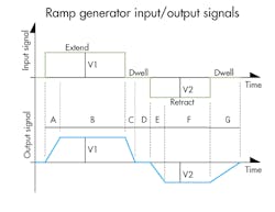
A: The ramp control is a special purpose signal conditioner that provides rudimentary, but effective, acceleration control. For example, imagine a machine axis powered by a hydraulic cylinder controlled by a proportional joystick. If the operator suddenly shifts the joystick to extend, retract, or stop the cylinder (the upper plot in the illustration), the axis will, with equal suddenness, accelerate — perhaps even causing damage.
The ramp control would be placed between the joystick output and the proportional valve’s input. When the ramp generator circuit receives a sudden (step) command, it does not simply amplify the signal and send it on. Instead, the output gradually rises or falls (ramps) to reach the input (the lower plot in the illustration), and, thus, gradually shifts the proportional valve to gradually accelerate the cylinder. It provides smooth starts and stops. User adjustments are available to control the ramp time on and ramp time off, and normally in both directions of hydraulic actuator motion.
Q: What is a buffer?
A: A buffer is an electronic device that isolates one device from another. An amplifier is a form of buffer. The simple explanation is that what changes on the input is immediately felt at the output, but what changes on the output is not felt on the input. Your car provides an analogous situation. If you step on the gas your car accelerates. But if you encounter a hill, you do not feel it in your foot. The engine feels it, and you may think you feel it in your foot as the engine strains to make a steep grade, but that’s all psychological. The engine, in its function as an amplifier, “buffers” your foot and leg from the strains of the engine and the hill.

