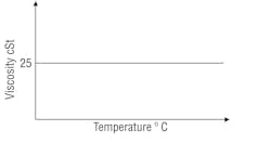
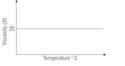
Whenever I present hydraulic maintenance training, a concept I always enjoy explaining to my students is what I call the perfect hydraulic fluid. And it’s very simple. The perfect hydraulic fluid would have a viscosity index (the change in a fluid’s viscosity relative to temperature) represented by a horizontal line intercepting the Y axis at 25 cSt, Exhibit 1.
Exhibit 1. Temperature-viscosity diagram of the perfect hydraulic fluid.
Of course, no such fluid exists and I don’t expect that such a fluid will be developed in my lifetime. But if such a fluid was developed, its creator would have the key to a gold mine.
Fluid viscosity is one of the factors that determines whether full-film lubrication is achieved and maintained. If load and surface speed remain constant, but elevated operating temperature causes viscosity to fall below that required to maintain a hydrodynamic film, boundary lubrication occurs with the possibility of friction and adhesive wear.
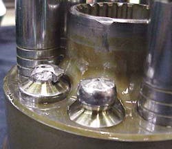
Exhibit 2 shows how this can manifest itself in an axial piston pump. Gold-colored varnish deposits are evidence that this hydraulic system has been operating over-temperature. Due to low fluid viscosity, the lubricating oil-film between piston and its bore has been lost. The resulting friction has super-heated the piston causing it to expand in its bore to the point of interference. Once this happens the tensile force pulls the slipper from the piston — causing catastrophic failure.
Exhibit 2. Catastrophic failure caused by low fluid viscosity
Exhibit 3 lists typical optimum and permissible viscosity values for an axial piston pump. Note the optimum viscosity range is 16 to 36 cSt. This is the viscosity range where the system will operate most efficiently — highest ratio of output power to input power. Stated differently, this is the viscosity range where fluid friction, mechanical friction, and volumetric losses are optimal for system performance.
Exhibit 3. Typical viscosity values for axial-piston pumps
But exhibit 3 only tells us half the story. There’s critical information missing. We need to know what operating oil temperature equates to each of these viscosity numbers.
To establish this, we need to consider the weight of the fluid in the system and its viscosity index – represented by its gradient on a temperature / viscosity diagram. The flatter the line, the wider the allowable operating temperature range – for both optimum and permissible viscosity.
Here’s where the perfect hydraulic fluid comes in. If you could use a fluid that “flat-lined” on a temperature / viscosity diagram at 25 cSt, as shown in Exhibit 1, a significant variable is removed and problems arising from insufficient fluid viscosity are instantly solved. And that would we worth paying good money for!
| Exhibit 3. Viscosity value | cSt |
|---|---|
| Minimum permissible | 10 |
| Minimum optimum | 16 |
| Optimum bearing life | 25 |
| Maximum optimum | 36 |
| Maximum permissible | 1000 |
Alas, such a “magic pill” solution is not available to us right now. So we can’t control the rate of change of viscosity with temperature — or not to the ideal degree at least. But we can control operating temperature. So here’s another ideal: the climate controlled hydraulic system.
Most us have driven or ridden in an automobile fitted with climate control. You dial in say, 22°C (72°F) and regardless of whether it’s snowing outside or hot enough to fry an egg, the climate control heats or cools the auto’s interior to maintain the selected temperature.
What if your hydraulic equipment had a similar system? You tell a computer the weight and viscosity index of the fluid you’re using and then select the viscosity you want the system to run at – say 25 cSt. Then, regardless of whether its summer or winter and the amount of heat load (internal leakage) on the system, the “climate control” would heat or cool the oil as necessary to maintain optimum viscosity. It’s possible, it’s just not very practical.
So with the perfect hydraulic fluid not available, and the climate controlled hydraulic system not feasible in most applications, human intervention is required. Someone has to do some leg work.
Some of the variables that must be considered include:
• starting viscosity at minimum ambient temperature,
• maximum expected operating temperature — which is influenced by system efficiency, installed cooling capacity and maximum ambient temperature, and
• permissible and optimum viscosity values for individual components in the system.
Once all these variables have been taken into account and a fluid with a suitable weight and viscosity index has been selected, an additional column of information can be added to Exhibit 3 so it looks like that shown in Exhibit 4.
Exhibit 4. Viscosity with corresponding temperature values
Having defined the operating parameters shown in Exhibit 4 for a specific piece of hydraulic equipment, damage caused by low or high fluid viscosity can be prevented by installing fluid temperature alarms or shutoff controls.
In the absence of the perfect hydraulic fluid, and short of installing climate control on all hydraulic equipment, this is the only way to ensure failures similar to that shown in Exhibit 2 don’t happen on your equipment.
For more information about hydraulic failures and how to prevent them, go to: www.PreventingHydraulicFailures.com
Part 2 of The Perfect Hydraulic Fluid
You may have done this experiment at school: your science teacher gives you a plastic syringe. With the plunger retracted she tells you to block the outlet with your finger and then attempt to close the plunger. You discover you are able to compress the air in the syringe by a significant amount.
She then tells you to repeat the experiment with the syringe full of water. This time the result is very different. No matter how hard you try, you discover you can’t compress the water in the syringe.
Seeing is believing. And to a 12 year old this experiment demonstrates, quite dramatically, that gases are highly compressible and liquids are apparently incompressible. By the way – if you didn’t do this experiment at school - you can try it at home!
The effectiveness of this simple physics experiment is illustrated by the fact that in my work as a fluid power engineer I regularly meet people who believe liquids, including hydraulic oil, are incompressible. But it’s not their fault. I certainly don’t remember my science teacher qualifying the obvious results of this experiment by explaining, compared to gases; liquids are highly incompressible – but compressible nonetheless!
In my previous column in H&P, I talked about the perfect hydraulic fluid with respect to viscosity. This ideal fluid would have a constant viscosity of 25 centistokes — regardless of its temperature. Another property of this ideal but non-existent hydraulic fluid would be perfect stiffness — just like the apparent stiffness of the water in the syringe in our school science experiment.
A fluid’s compressibility is defined by its bulk modulus of elasticity — which is the reciprocal of compressibility. The bulk modulus of a fluid is non-linear — meaning when the change in volume with pressure is plotted on a graph, the result is a curve rather than a straight line.
Bulk modulus is further defined as isothermal — where the heat associated with compression is dissipated (constant temperature) or isentropic — where the heat associated with compression is not dissipated and so both pressure and thermal expansion are considered. Isentropic can be thought of as dynamic bulk modulus and isothermal as static bulk modulus. The former is most pertinent to modern, high-response hydraulic systems.
The negatives of compression
Bulk modulus is an inherent property of the oil and therefore an inherent inefficiency of the hydraulic system. The fluid in the pipeline and actuator must be pressurized — and therefore compressed — before it will move a load. Because this compression of the fluid requires work at the input — which cannot be converted to useful work at the output, it is lost work and therefore a contributing factor to the overall inefficiency of the hydraulic system. The larger the actuator and the faster its required response time the higher the inefficiency attributable to bulk modulus.
And in high-performance, closed-loop electro-hydraulic systems, deforming oil volumes affect dynamic response and can cause stability problems such as self-oscillation.
Minimizing the losses
Bulk modulus varies with base stock, for example naphthenic oils have a higher bulk modulus than paraffinics. And unlike viscosity index, bulk modulus cannot be improved with additives. But there are things we can do to minimize the inefficiencies and potential control problems associated with compression of the fluid.
The first is to ensure the hydraulic machine doesn’t run hot. Compressibility of the fluid increases with temperature. Mineral hydraulic oil is around 30 percent more compressible at 100°C than it is at 20°C. Of course, there are many good reasons why you should never allow hydraulic equipment to run hot – many of which I have discussed in previous MRO articles. Reduced bulk modulus is another one.
The second is to prevent conditions that cause aeration. From our school science experiment, we understand that air is 10,000 times more compressible than oil. One percent of entrained air by volume can reduce the isothermal bulk modulus of the oil to as low as 25 percent of its normal value.
It is important at this point to distinguish between entrained air – bubbles typically with a diameter of less than one millimeter dispersed through out the fluid – and dissolved air. Hydraulic oil typically contains between 6 and 12 percent of dissolved air by volume. This dissolved air has no measurable effect on bulk modulus (or viscosity) – provided it stays in solution.
While controlling aeration is in no small part a design issue – for example, the amount of dwell time the fluid has in the tank, proper maintenance also plays an important role. Dissolved air comes out of solution as temperature increases. This is another reason to maintain appropriate and stable operating temperatures. Oxidative degradation and water contamination inhibit the oil’s ability to release air, often resulting in an increase in entrained air volume.
Conclusion
Given the perfect hydraulic fluid – one with infinite stiffness, does not exist, and in view of the current trend towards hydraulic equipment with higher operating pressures, higher power density and faster response, it’s more important than ever to consider the operational effects of fluid compressibility on the hydraulic equipment you design, maintain, repair or operate.
Brendan Casey is the founder of HydraulicSupermarket.com and the author of Insider Secrets to Hydraulics, Preventing Hydraulic Failures, Hydraulics Made Easy, and Advanced Hydraulic Control. A fluid power specialist with an MBA, he has more than 20 years experience in the design, maintenance, and repair of mobile and industrial hydraulic equipment.
About the Author

Leaders relevant to this article:


