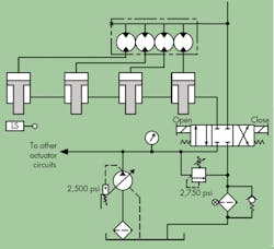
An older four-post vertical press with a 6-ft daylight opening was designed with one cylinder on each corner of its platen. The cylinders extended to close the press and retracted to open. To keep the platen somewhat square and parallel with the press’s bed plate, a four-section gear-type flow divider was used to feed the cap end of the four cylinders.
Unfortunately, the plant’s maintenance crew had to replace the flow divider about once a month. The flow divider would crack at any one of the gear housing rings, and there wasn’t any pattern to which ring failed.
The crew was told to lower the press to the fully closed position and install a new flow divider. Sometimes the flow divider failed even before the crew finished bleeding air from the cylinder lines.
All hydraulic functions of the press were powered by a pressure-compensated piston pump set at 2,500 psi. The system’s safety relief valve was set to open at 2,750 psi, and the flow divider itself was designed to operate safely at pressures to 3,000 psi.
The flow divider circuit used a three-position closed-center directional valve with a limit switch to detect if the press drifted down 1 to 2 in. from full open. When this did occur, the limit switch would shift the directional valve to return the press back to the full-open position and hold it there for about 10 sec. The directional valve then would shift back to the center position.
Other than a few leaking fittings, the press seemed to be well maintained, so why was the flow divider failing so frequently?
Related
This file type includes high resolution graphics and schematics when applicable.
Solution to flow dividers keep breaking
Gear-type flow dividers work well, but if any one of the gear section outlet piping leaks, aerates, or builds pressure before the other sections, pressure intensification can occur. This does not happen on spool type dividers.
Take a 2-section gear type divider driving two cylinders. If one cylinder bottoms out, pressure will build in that cylinder. However, if the other outlet port has no pressure on it, this gear set acts like a hydraulic motor that has a drive shaft driving the other pressurized gear set. This torque along with the incoming pressure could intensify the pressurized cylinder to twice the system pressure. A 4-section divider could intensify a pressured line four times the incoming pressure.
This type of application requires a safety relief in each flow divider outlet to allow the pressure to maximize at a safe level and allow the flow divider to continue to turn and fully extend all the cylinders. The relief valves can act like a reset devise each time the cycle is completed.
Installing flow dividers requires care and a good understanding of how to bleed air from and synchronize the system to prevent pressure intensification.
In this case, the press maintenance group did not realize the importance of fixing any leaks in the cylinder lines and the correct installation procedure. However, the designer of the system should have used flow dividers with individual reliefs in the outlet lines of each section to prevent this problem.


