A survey by the U.S. Department of Energy reveals that 10% of all energy consumed by the average industrial facility is used to generate compressed air. That’s on average, so some plants may be closer to 30%.
Clearly, making the most efficient use of compressed air will lead to significant energy savings. Yet, in many cases, as much as 30% of compressed air is wasted. Although much of this waste relates to the compressor itself, this discussion will help identify other areas where waste can be prevented, ultimately reducing your plant’s electrical consumption.
Eliminate Leaks in Piping and Components
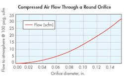
Air leaks are a significant cause of wasted energy in compressed-air systems—as much as 20 to 30%. In addition to wasting energy, leaks also reduce working pressure, which lowers productivity. Based on a U.S. Department of Energy calculation, and using an electricity cost of $0.0723/kW-hr, a single ¼-in. leak adds up to more than $5,600/yr in wasted energy. Many such leaks can be repaired in less than an hour, so the payback is immense.
Areas susceptible to leaks include:
Pipework, fittings, flanges, and manifolds—Large leaks are often found at connection points, both in the main distribution system and in circuit branches. Using several quick-acting connectors together to form manifolds may cause leaks due to worn connectors and poorly jointed pipework.
Hoses and couplings—Leaks can occur from hose damaged by abrasion against surrounding objects, deterioration of the hose material, and strain on the joint because the hose is too long or too short.
Poorly maintained components—Pneumatic components are rated for a maximum number of cycles or hours of service life. Therefore, worn seals in cylinders, valves, and regulators that lead to internal and external leaks certainly can waste money.
Condensate drain valves—Large amounts of air may be lost when drain valves stick open or are left open intentionally. These can often be found in remote parts of the system where condensate collects.
Systems left pressurized when not in use—Leaks may have to go uncorrected in some machines—such as presses and drop hammers—because they are critical to production or expensive to repair. When this is the case, be sure they are isolated from the main compressed-air system when not in use. Simple shutoff valves or electrically operated dump valves are cost-effective ways to isolate a machine from the rest of the compressed-air supply.
Reducing and Eliminating Leaks
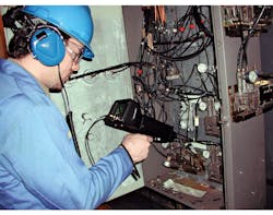
A leak-reduction program starts with a survey of the compressed-air system. Inspect during quiet hours. Listen for pipework or tool leaks, and examine hoses and couplings. A low-tech fix is to spray soapy water or other solution on pipe joints and watch for bubbles. A more effective method is to use a handheld ultrasonic leak detector. Outsourcing the inspection to a compressed-air auditing expert can also quickly pay for itself many times over.
Next, create a plan and set targets for leakage reduction. Publicize the amount of money being squandered by the leakage and how much you intend to save. Some plant managers divide the site into zones, fitting air-consumption meters and charging each area for its air usage. Targets can then easily be set to reduce energy loss due to leaks. An ongoing maintenance program that implements a site-wide awareness program leads to long-continuing savings.
Put an End to Misuse
The second major source of compressed-air waste is to use it as a power source just because it is available, even though more efficient sources for a particular application may be readily accessible. Some examples include inefficiently creating vacuum for ejecting faulty parts or removing water, dirt, or powder from products. There may be better alternatives for these applications. If compressed air is the appropriate choice for blowoff, it should be done at the lowest pressure that is effective.
New misuses in an existing operation can often be seen as increased air demand or more frequent compressor cycling. Where a process has air passing to atmosphere, a flow meter can be installed in the line to measure air usage. To identify existing misuses, all areas of the plant need to be surveyed, asking the question: “Is this an effective use of air?”
Where air nozzles must be used, such as blowing loose flour off loaves of bread, then ensure that the distance between the exit nozzle and the product is as short as possible—this will allow use of a lower supply pressure. The nozzle should be directed only at the area needed. Ensure the mains feed line to a number of nozzles is of sufficient diameter so that it does not restrict the outlet flow.
For these types of solutions, be sure control valves and sensors are fitted so that flow only occurs when the product is at the application point. No flow should occur during the gaps between product on the conveyor, or during work breaks.
Air-saver nozzles entrain and accelerate air within their mechanism to produce the desired outputs with reduced supply pressures. They can reduce compressed-air usage up to twenty-fold.
In some cases, the solution may be to use air, but not compressed air. Dedicated air blowers or vacuum pumps may well prove more cost-effective.
Excessive Pressure
Many systems run at full line pressure, controlled only by the pressure switch on the compressor. Every item of pneumatic equipment has an optimum operating pressure and flow. Usage outside of these parameters will shorten equipment life due to increased loading and wear, and will increase running costs.
Savings can be realized by eliminating over-pressurization in air tools, control valves, clamping cylinders, and on the return stroke of large double-acting cylinders.
Double-acting cylinders usually perform only on the extension stroke. When no work is being done, or longer reset times are possible, the return stroke can be at a lower pressure. For large bore, long stroke, or multiple cylinder systems, it can result in considerable air savings. Using a regulator to reduce return stroke pressure can be a fast payback solution.
Flow saving with valves is possible by simply reducing the applied pressure to the rated conductance of the valve. It is important to note the valve operating duration (i.e., time that flow occurs) to ensure optimal flow saving. Usually this figure is small, but for multiple valve installations or rapidly cycling valves with long pipe runs, the total saving can add up.
Finally, ensure that all new plant processes and equipment are examined for optimum operating conditions and pressure control prior to installation. This should result in increased tool life as well as reduced energy costs.
Pressure Drop
Pressure drop can be defined as the loss in a system of power available to do work. In practice, it is shown by low pressure in parts of the system. Operators often compensate for low pressure by increasing generation pressure or turning up regulators, rather than identifying and solving the problems that cause pressure drop.
The potential energy generated by compressing air is dissipated through friction and heat losses as it is pushed through all components of the system. Thus, systems must be designed and maintained to minimize pressure drop. Every 1 bar of unnecessary pressure drop leads to an increase of 7% in generating costs. The two main areas that incur pressure drop are pipework and filtration.
Plumbing—Pressure drop in pipework mainly results from friction of the air molecules with the surface of the pipe. If the pipe is too small for the volume of flow, the velocity of the air will be very high and lead to a big loss in power. Energy is also lost when there is a change in flow direction, e.g. elbows, junctions, and shut-off valves.
Don’t over flow the pipework. Keep velocity below 6 m/s in mains. Simplify the pipework to avoid elbows. A 90-degree elbow causes the same pressure drop as 1.6 m of straight pipe. Fit low-resistance valves; a full-flow ball valve equates to just 0.4 m of pipe—less than half the resistance of a gate valve.
—Filtration is an essential part of the conditioning in a compressed-air system. If not protected from water, particles, and degraded compressor oils, machines will quickly break down. There are three ways to minimize pressure drop caused by filtration:
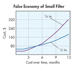
First, look for the right size filter unit. As with pipework, if a filter unit is too small for the required flow, it will cause a higher pressure drop. When new, a general-purpose filter should create no more than 0.1-bar pressure drop. Specifying a smaller filter may save a little money initially, but its cost of ownership will quickly escalate in the form of higher pressure drop. And operating cost will further increase because the smaller surface area of the element will become blocked more quickly.
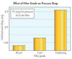
Second, use the right level of filtration. Fine filters will pose greater resistance to flow than their coarse counterparts. Most air tools require filtration of only about 40 µm. Therefore, it makes sense not to use a 5-µm filter in such applications. When equipment requires finer filtration, place the finer filters as close to the tool as possible. This allows you to use the most appropriate size filter.
Furthermore, there is no need to filter the whole air line or branch line to this 5-µm standard. Doing so will increase the flow requirement and require a larger filter, which in turn hikes acquisition and maintenance costs as well as incurs more pressure loss for the whole system downstream of it.
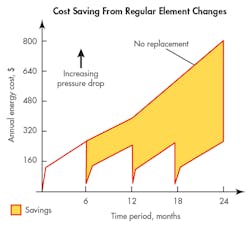
Finally, look for dirty filter elements. As more particles become trapped within the filter element, it increases pressure drop. Operators often try to compensate by turning up the regulator to boost pressure, and that higher pressure ramps up costs.
Fitting simple pneumatic or electrical pressure-drop indicators can signal when pressure is dropping from a blocked filter element. Changing the elements at this point creates significant energy savings. It is good practice to change the filter elements at regular intervals. This will ensure that energy waste is kept to a minimum and correct air quality is delivered.
Any new plant should be installed with the right level of air quality in mind, using instrument quality air only where the application demands it. Delivering very dry high-quality air to all areas of the site is costly and should be avoided.
Devoting even a few maintenance hours to repair leaks, avoid misuse of compressed air, reduce over-pressurization, and control pressure drop can result in savings of tens of thousands of dollars each year.
Bradlee Dittmer is Product Marketing Manager at IMI Precision Engineering, Littleton, Colo. For more information, call (303) 794-5000 or visit the company's website.
About the Author

Leaders relevant to this article:
