Sizing Accumulators and HPUs for a Cylinder’s Sinusoidal Motion
Sizing the hydraulic power unit (HPU) and accumulator needed for a cylinder’s sinusoidal motion is easy. Three formulas define the parameters: one for the HPU, two for accumulator. It is interesting how these formulas are derived and what they reveal. (If you don’t like math, skip to the end for a summary).
Sinusoidal motion requires a sine function that calculate the position for the target generator. The sine function returns values from −1 to 1 as a function of time.
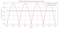
Because oil is required to extend or retract the cylinder, the absolute value of the sine function is used to ensure the returned value is always positive; oil is always needed in a real system. This is a full-wave rectified sine wave. At times, the full-wave rectified sine wave’s value exceeds the average and at times it’s below average. The HPU and accumulator could be sized for peak values, but that costs more. So, what are the minimum or average or average sizes for the HPU and accumulator?
To find the average value, the full wave rectified sine function must be integrated with respect to time, t, for one cycle and then divided by the time over which the sine function was integrated. The sine wave’s absolute value must be integrated because the system uses oil to extend and retract. This also assumes a double rodded cylinder is being used; that is, actuator areas are identical.
So far, the piston’s amplitude and area are not being used; they will be applied later. The result is the average value of a full wave rectified sine wave. The average value is 2/π, or about 0.64 of the peak value of 1.
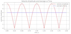
The amount of oil being used is proportional to the sine function’s rate of change. Find this by taking the derivative of the sine function. The result is the rate of change of the full wave rectified value.
Fwr rate(t) = Abs(2π cos(2πHz ⋅ t ))
The average value full wave rectified value is
Avg fwr rate = 4 ⋅ Hz
The amplitude of the sine wave and cylinder’s area are used to calculate flows:
After simplifying, average flow is:
Avg flow = (4Hz) Amplitude ⋅ Area
Average flow is a minimum flow, assuming an accumulator smooths the flow between times of peak and no flow.
The next step is calculating the variation in the volume of oil or gas in the accumulator. This requires integrating (adding up) the difference between average and actual flow demands over a cycle. This can be done using calculus or a spreadsheet.
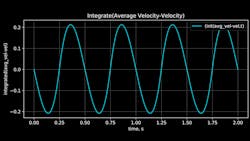
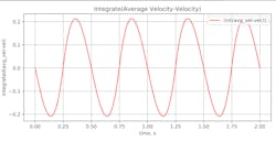
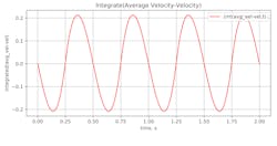
This is the integrated difference between the average flow into the accumulator minus the out flow. What this graph shows is that the oil volume changed between plus and minus 0.21 times the amplitude times the area of the cylinder. This makes calculating the difference in volume easy.
Volume change = (4.2) ⋅ Amplitude ⋅ Area
The change in the volume of gas or oil in the accumulator is required to calculate the accumulator size and pre-charge pressure. First, the amount of gas in the accumulator at system pressure must be calculated. The accumulator’s task is to keep the system pressure relatively constant. Therefore, we should minimize the change in volume of the initial volume of gas. It is best if pressure does not drop more than 10%. We must use the adiabatic gas law to find the pressure change.
The mass of the gas isn’t changing, so there is no heat transfer. So, simplify the adiabatic gas law to calculate the desired gas volume when the accumulator is at system pressure. The basic formula for an adiabatic process is
P ⋅ Vγ = K
Where γ is a constant called the adiabatic index and is 1.4 for nitrogen.
To calculate the volume of gas when the accumulator is at system pressure, it takes two equations, one for when the accumulator is at system pressure, and another for when the accumulator volume has expanded to the pre-charge volume plus the calculated volume change (from above). both equations are equal to K, so the two equations must be equal to each other. Now we can solve for the pre-charge volume:
Ps ⋅ Vol01.4 = 0.9 ⋅ Ps ⋅ (Vol0 + Δv)1.4
Where Ps is the supply pressure, Vol0 is the pre-charge volume and Δv is the volume change of gas in the accumulator.
Solving for the minimum pre-charge volume, Vol0, as a function of the volume change is complicated. Skipping some steps, the result is that the pre-charge volume should be at least 12.8 times the volume change. The accumulator size must be more than the pre-charge volume plus the volume change, plus a little more to make sure the accumulator never goes completely empty. For safety, the accumulator size should be about 15 times the volume change. Multiplying the volume change by 12.8, the accumulator size should be at least:
Accumulator volume = 12.8 ⋅ 4.21 ⋅ Amplitude ⋅ Area
Accumulator volume = 63.15 ⋅ Amplitude ⋅ Area
Assuming the minimum accumulator size, the pre-charge pressure should be.
Precharge = 0.8 ⋅ System pressure
Chances are, you won’t find an accumulator this exact size, so the next biggest size is used. This reduces the pre-charge pressure because actual accumulator size will likely exceed 15 times the volume change.
There is an option now. You can increase the pre-charge volume. A good choice is to use the maximum value of either 0.9 × accumulator volume or 12.8 × volume change. This reduces pressure fluctuations to less than 10%.
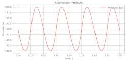
The resulting simulation will look something like this assuming a supply pressure of 200 bar, an amplitude stroke of 10 mm, a 100 mm cylinder diameter, a 70-mm rod diameter and a double rodded cylinder.
The plot shows the accumulator gas volume. The accumulator size was calculated to be 0.0253 L, but this had to be rounded up to the next available size, which is 0.3 L. Most sinusoidal testing accumulators are small.
Initially, more oil leaves the accumulator than enters, so gas volume is increasing.
As the gas volume increases, accumulator pressure gets smaller. Notice the pressure drop is not 10%. That’s because we are using a three-liter accumulator rather than the calculated 2.53-liter accumulator.
For those that skipped to here, the three formulas are:
Minimum flow = Avg flow = 4Hz ⋅ Amplitude ⋅ Area
Accumulator volume = 63.15 ⋅ Amplitude ⋅ Area
Precharge = 0.8 ⋅ System pressure
Most of these calculations are theoretical minimums. Usually this is not a problem because accumulator and pump sizes must be rounded up to the next available standard size. But if in doubt, select the next available size.
Another issue is the minimum pump size. This result assumes the pump can supply the minimum flow. This only happens with fixed-displacement or servo-controlled pumps. Pressure-compensated pumps will not supply the maximum flow until pressure has dropped to the bottom of the proportional band. When pressure is at the desired supply pressure, the swash plate will be in a neutral position and generating little or no flow. To compensate, count on getting a pump that is twice as big. When the pressure drop is about half the pressure band, half the flow is generated, but if the pump is rated at twice as much as necessary, the required flow is generated.
The other thing to consider is that amplitude and frequency may change. The pump calculations should be done for the worst-use case. A servo-controlled fixed-displacement pump can generate the average flow at a constant rate without having to oversize the pump.
Peter Nachtwey is president of Delta Computer Systems Inc.
About the Author
Peter Nachtwey
President,
Peter Nachtwey has more than 35 years of experience developing industrial control systems for hydraulic, electric, and pneumatic applications. He graduated from Oregon State University in 1975 with a BSEE and served as an officer in the U.S. Navy until 1980. He became president of Delta Computer Systems Inc. in 1992. In addition to leading Delta’s engineering and R&D programs, he contributes widely to the mathematical understanding of control theory, especially in fluid power systems. He has also presented technical papers for IFPE, NFPA, FPDA, and various global technical conferences.

Leaders relevant to this article:
