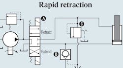
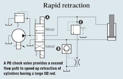
Balanced flow during retraction can be achieved with the circuit shown here. When the appropriate pressure (several hundred psi) is applied to the rod end, this pressure opens sequence valve
C and feeds pressurized pilot oil into pilot-operated check valve
B. Valve
B, which has a large flow capacity, opens to provide a second path for returning oil directly to tank, in addition to the flow path through directional valve
A. The resulting second-path flow through check valve
B increases return oil flow three 3 to five times, and with low pressure loss.
Sequence valve C is set at a high enough opening pressure so that minor backpressure during extension does not inadvertently open check valve B.
This circuit design permits directional valve A to be sized according to the pump flow rather than the much larger volume of return flow during retraction. For the cylinder first described, pilot-operated check valve B may draw more than 100 gpm out of the circuit during retraction.
This circuit was submitted by Lew Tomer, of Fluid Controls Inc., Mentor, Ohio, and was originally published in the January 1984 issue of Hydraulics & Pneumatics.


