Use a flow divider to double cylinder speed
A cylinder in a transfer unit on a production line transferred parts from an inbound conveyor to a sizing die, then to an outbound conveyor. Due to changes made upstream, the production line was now “waiting” for the transfer unit.
Our manufacturing engineering department wanted the transfer cylinder to operate twice as fast, to be retro-fitted inexpensively with minimal downtime. The cylinder’s valves and piping were already carrying maximum flow capacity; any increase in flow would require larger valves and piping, which would be expensive. The cylinder’s 3¼-in.bore with a 1⅜-in. rod diameter ruled out a regenerative circuit because the bore-to-rod ratio was not 2:1. Also, we didn’t have a smaller bore cylinder at our disposal with the required 72-in. stroke. In addition, manufacturing engineering wanted the solution immediately.
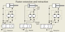
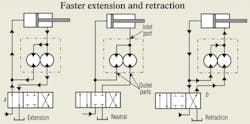
To increase cylinder speed at minimal cost and virtually no downtime, we used the accompanying circuit with great success. The circuit used a standard equal-flow, two-section gear-type flow divider connected in the rod-end line of the cylinder. The normal inlet port of the flow divider is connected to the cylinder rod-end port. One outlet port is connected to the directional control valve, and the other outlet port is teed into the line from the cap-end cylinder port to the directional valve. (The hookup took place at lunch break; the machine was ready to run again before lunch was over.)
When the cylinder extends (valve position a), oil from the rod end enters the flow divider. Half flows to tank through the directional valve, while the other half mixes with the pump supply and flows to the cap end.
Thus, we built a regenerative circuit without using a 2:1 rod cylinder. As in any regenerative circuit, the cylinder requires about twice the pressure — compared to a non-regenerative circuit — to extend at this increased speed. The actual speed gain was about 90% instead of 100%. It is lower, I believe, due to internal slippage in the flow divider.
With the directional valve shifted to position b, pump flow into one outlet port of the flow divider flows to the cylinder rod end. Oil from the cap end tries to return to tank, but mainly flows to the other outlet port of the flow divider and mixes with pump flow to increase cylinder speed about 95%. It actually takes 150 psi less pressure to retract the cylinder, probably because flow to tank is less, which reduces backpressure.
Here are some observations about this circuit that are not immediately apparent:
• Because the flow divider is between the actuator and the control valve, the valve does not have to handle high flows.
• Even though we are dealing with twice the flow, the reservoir, pump, valve, and piping need not be increased in size to avoid problems from excessive heat generation.
• We have used this same circuit with a sequence valve and a pilot-operated check valve (to remove the flow divider from the circuit when the load is contacted) to obtain maximum force during extension.
This circuit has been in operation continuously for many months, with no downtime or problems.
This information is excerpted from the archives of Bud Trinkel, deceased, a former consultant, frequent contributor to Hydraulics & Pneumatics, and author of two e-books on our website.


