Unique hydraulic cylinder design helps position rail cars for loading and unloading
Appeared in print as "Cylinders move in single file"
When a section of rail cars enters a terminal for unloading, one method of moving freight cars from one location to another is to use a yard engine or track mobile. Even though it’s not the most efficient or productive method, this equipment has been the traditional solution. The procedure also requires using more than one person, regular maintenance, and is not as safe as more modern methods.
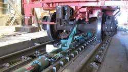
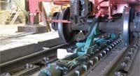
A much more effective method of indexing rail cars is to use a hydraulic rail car mover, designed and manufactured by Calbrandt Inc., Delano, Minn. Calbrandt’s rail car mover is used for positioning a strand of up to sixty 143-ton rail cars for loading or unloading bulk media, such as grain, oil, coal, wood chips, or gases. The machine has arms (called dogs) that rise from ground level and push on the axle of a rail car to move it forward with controlled motion to a desired position. Depending on the setup, it can move cars at speeds to 60 ft/min and generate 75,000-lb of thrust.
The rail car mover provides higher productivity than using a yard engine or track mobile because the person controlling the movement stands right next to where the work is being done, making it easy to position cars right where they need to be. With traditional equipment, this person would give verbal commands to a second person operating a yard engine or track mobile. The rail car mover also requires less maintenance compared to using a track mobile for positioning rail cars. The mover is also safer because it is less likely to create sparks, which could trigger an explosion when working with volatile media.
Sequence of operation
The operator of a rail car mover stands near the area where the loading or unloading will occur. This allows the operator to view the position of the car directly. Operating sequences are provided by an Allen-Bradley PLC through a human-machine interface. The PLC, in turn, commands solenoid-operated hydraulic valves.
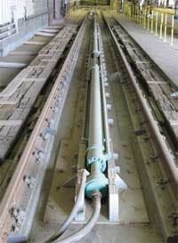
Calbrandt offers two types of rail car movers, depending on productivity required for the respective installation. An indexer type pushes the axle of a rail car using a single length of hydraulic cylinders mounted end-to-end and positioned parallel to the rail. A 118 -in. bore hydraulic cylinder with 6-in. stroke raises an axle dog from the floor to engage the axle of the rail car, then the colinear cylinders extend to move the car.
The axle dog then drops back below floor level, and the cylinders retract back to their home position while the rail car is loaded or unloaded. The machine is then set to begin another push cycle. A progressor type mover uses a pair of cylinder assemblies to push a rail car in a continuous motion along the length of the track. While one set of cylinders is retracting, the other is extending — a sort of walking motion that moves cars at a uniform speed.
In either case, the car mover is configured to move cars in either direction along the rails, with cylinder extension or retraction as the work stroke. The system can generate up to 55,000 lb of thrust at a system pressure of 1660 psi during extension or 3185 psi during retraction.
Special cylinders make the connection
Hydraulics was chosen for this application because it is the only form of power transmission that can fit into the narrow confines of the application and still generate more than 25 tons of thrust. That’s not unusual for hydraulics, but the cylinders, and their arrangement, are.
Calbrandt’s standard rail car mover consists of five cylinders mounted end-to-end in a colinear arrangement. The first cylinder is stationary, and when its rod extends, it pushes on the cap end of the second cylinder. Likewise, the rod of the second cylinder pushes on the cap end of the third cylinder, and so on. This means that, theoretically, the rod end of the second cylinder moves at twice the relative ground velocity as the first one. This is because the body of the second cylinder (which is mounted on rollers, as are the third, fourth, and fifth cylinders) moves at the speed of the first cylinder’s rod, and the rod of second cylinder extends at that same speed. Therefore, the rod end of the fifth cylinder moves at five times the ground velocity as the first one.
In actuality, the stroke speed of any given cylinder varies. The piston acting against the least resistance will move. However, the net result is uniform motion from the cylinders sharing fluid routed in parallel.
However, probably even more unusual is the plumbing arrangement. The pump and tank lines from the hydraulic power unit are both connected to the end cap of the first cylinder. Both fluid paths in the cylinder are routed so that they exit from its rod end. A flange on the rod end connects to the end cap of the next successive cylinder and routes fluid into its pump and tank ports, as shown in the illustration. This configuration is repeated for the third and fourth cylinders, and the fifth cylinder simply has a connection to a mechanical linkage on its rod end.
All five cylinders have a 612-in. bore, 188-in. stroke, and 412-in. rod diameter. The rod has a 12-in. wall thickness and 112-in. ID center tube — through which fluid to extend the rod flows, and around which fluid to retract the rod flows. Each cylinder requires 13 gal of fluid to move from fully extended to fully retracted. All cylinders have nitrided rods and a robust sealing package to withstand the ambient conditions and dirty atmosphere.
Calvin Brandt, president of Calbrandt, said a telescoping cylinder could have performed functionally similar to the colinear cylinders. However, the multiple stages of motion and the large piston area needed to generate the high thrust would have required a telescoping cylinder too large to fit between the rails.
Brandt pointed out yet another unusual design aspect of the mover. “We raise and lower the dogs on the carriage by controlling the pressure in the hydraulic lines. Low pressure drops the dogs and 1200 psi raises them. We do this with using counterbalance valves. We bypass the counterbalance valves to drop the dogs. However, when pushing pressure goes above 1200 psi, the counterbalance valve in that direction opens, so there is no residual pressure drop. It’s a simple solution, and it works quite well.
For more information, call Aggressive Hydraulics at (763) 792-4000 or visit www.aggressivehydraulics.com.
For more information on Calbrandt Inc., visit www.calbrandt.com.
About the Author
Paul Johnson
President

Leaders relevant to this article:


