Getting your system in sync Part 1
Imagine trying to control a huge container of molten metal that must remain perfectly level as it is lowered or moved across a factory floor. Cylinders controlling this motion could each be hooked up with linear displacement transducers, tied into a control system — with some sacrifices in speed, not to mention high costs. But there are many other ways to synchronize multiple actuator functions within hydraulic systems. These include: valve-type flow dividers and divider/combiners, rotary external gear flow divider/combiners, and rephasing type hydraulic cylinders.
Valve-type flow dividers
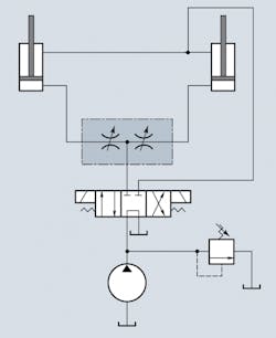
Flow divider valves are probably the most common type of component used for synchronization, both in open- and closed-loop hydraulic systems. Usually, these flow divider valves consist of two or more pressure-compensated flow control (PCFC) valves within the same envelope. These flow control valves are designed to split and/or combine the incoming flow according to a predetermined ratio. In most cases, the dividing ratio is 50/50, and the combining ratio is one to one.
Advantages — This style of divider offers a great deal of design flexibility: the function can easily be integrated into other or multiple components (valve blocks, valve and hydraulic manifolds, stack-type valves). It is also easy to build a simple on-off function into this design. This is typically accomplished by plumbing a basic two-position, two-way valve, or a two-position, three-way valve in parallel with the divider itself.
The valve-type divider can be a discrete component. As such, a remote mounting location or position may facilitate design and manufacturing. It is easy to build a hydraulic re-synchronizing feature into this design by virtue of a steering or makeup orifice. Lastly, this design offers the ability to control and operate both linear and rotary actuators.
Disadvantages — The valve-type flow divider/combiner is an additional component that must be added to the system above and beyond the cost of the other components required. There may also be other miscellaneous incremental costs associated with this approach (additional plumbing, etc.). Historically, the accuracy of valve-type flow divider/combiners has not been as precise as that of external-gear rotary units or re-phasing type cylinders. Other issues include an inability to transfer power and the need for additional space. Also, if a high degree of certainty regarding synchronization is desired, a mechanical connection between the actuators would be necessary.
Rotary external-gear type flow dividers
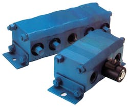
This is the next most commonly used component to achieve hydraulic synchronization. The dividing/combining ratio is always a function of the displacements of the rotating gear sets within the component. Thus, two gear sets with the same dis- placement would result in 50/50 di- vision, three of the same would yield 33.3/33.3/33.3, and four of the same would result in 25/25/25/25. Non-equal ratios — such as 60/40 or 75/25 — are possible, but these are generally uncommon.
Advantages — As this is a discrete component, it offers ease in location selection and mounting, and provides flexibility to both ma- chine designers and manufacturers. These units offer very high ac- curacy, typically somewhere between two to four times that of valve-type designs. There is also the ability to “transfer” hydraulic power between actuators, due to their pressure intensification effect.* They can be used to operate either linear or rotary actuators.
Hydraulic re-synchronization is possible by the use of a simple steering or synchronization orifice.
Disadvantages — As the divider/combiner is a discrete component from the actuator, there is an added cost, plus possible additional plumbing. Again, there is a potential parasitic power loss associated with hydraulic re- synchronization. In some circuits, protection against pressure intensification must be provided via relief valves or some other method. This is a significant point with rotary external-gear type flow dividers. As with the valve-type dividers, additional physical space is required. This may be an issue for designers of equipment with space, size, or weight constraints.
The external-gear rotary type flow divider/combiner is a positive- displacement type of device. Therefore, the flow is divided or combined according to ratios de- fined by the displacements of the rotating gear sets themselves. The flow division is completely independent of any inlet, outlet, or load pressures (up to the working pressure ratings of the various components, or as limited by relief valves). This allows transfer of hydraulic power from one load to another when load pressures change. The difference is not lost to heat or noise within the hydraulic system — provided, of course, that the intensified pressure does not exceed the system’s capabilities.
A 50/50 example
Assume a 50/50 divider/combiner is being used in divide mode. Input power is 20 gpm at 2000 psig, or 23.3 hp. Further assume that this divider is 100% efficient and that the load pressure for both actuators is 2000 psig. Each actuator will receive 10 gpm, according to the 50/50 division ratio.
Now assume the actuator load demands change. The load of actuator A increases by 1000 psig, the load of actuator B decreases by the same, and all other characteristics of the system do not change. Because of the design of the rotary flow divider, it continues to mechanically force 50/50 flow division, regardless of changes in load pressure. However, the power in must equal power out (assuming 100% component efficiency). Therefore, the new system conditions would be described by the equation, above right.
This equation illustrates that while the flow division has remained the same (50/50), some of the former power from actuator B (which now only sees 1000 psig at 10 gpm, or 5.8 hp) has been effectively transferred to actuator A (which now sees 3000 psig at 10 gpm, or 17.5 hp). The crucial point is that the total power, 23.3 hp, remains unchanged. This con- firms that the available power has effectively been transferred between the actuators, as opposed to being lost into the system as heat or noise.
Why is this power transfer possible with rotary-type dividers but not with valve-type dividers? The answer lies within the fundamental design and performance characteristics of each component. A flow-control valve controls flow by adjusting the size of an orifice or passageway that hydraulic fluid passes through. This inherently affects the pressure drop across that component. However, an external-gear rotary flow divider (or a re-phasing type hydraulic cylinder), is a positive-dis- placement type of device. It moves the same amount of hydraulic fluid per revolution (flow divider), or increment of stroke (re-phasing cylinder), regardless of inlet and outlet pressures.
This fundamental difference al- lows external gear rotary flow dividers and re-phasing cylinders to divide or combine hydraulic fluid independent of pressure changes. Consequently, a reduction in load pressure at one actuator can be effectively transferred to another, and not lost to heat or noise within the hydraulic system. Therefore, external gear rotary flow dividers or re-phasing type hydraulic cylinders provide better use of available power. Flow control valves simply do not have this capability.
Part 2 of this article looks more closely at rephasing cylinders.


