A Checklist for Matching Pneumatic Cylinders to Load Requirements
*Editor's Note: This article was originally published in 2013 and updated in June 2023.
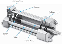
When applications involve linear motion, high speed, and moderate loads, pneumatic cylinders — also referred to as air cylinders — are often the first choice to provide the actuation. Compressed air is available as a utility at almost every industrial facility, and economical air cylinders can be obtained from many manufacturers.
One of the most fundamental fluid power components, pneumatic cylinders have evolved into an almost endless array of configurations, sizes, and special designs. Their versatility not only makes more innovative designs possible, but also brings many linear applications that would not be practical or possible without cylinders to life.
How to Properly Size Pneumatic Cylinders - 9 Crucial Guidelines
Pneumatic cylinders are simple devices, and calculating their theoretical force output is fairly straightforward. However, sizing a cylinder properly for a real-world application is more complex. Undersizing, for example, is a common mistake that results in sluggish performance and cycling problems in automated equipment. Oversizing a cylinder wastes energy by using more air than is necessary.
By following a few simple guidelines, you can quickly learn how to determine the right air cylinder to fit specific application needs.
Calculate the Force
The theoretical force output of a pneumatic cylinder is the product of the air pressure applied and usable piston area exposed to it,
F = P × A,
where F = force in lb, P = supply pressure in psi, and A = piston area in in.2
For example, a cylinder with a 1-1/2 in. bore supplied with 80 psi air would generate:
F = 80 × π(0.75)2
F = 141 lb.
Note that area is fixed once the cylinder is selected and installed. Pressure can be varied, but only over a limited range. Therefore, it behooves the designer to calculate force, and, hence, area, very carefully early in the project. Also note that the formula calculates the theoretical force output. Several factors can and will lower it in a real application. Several issues should also be kept in mind whenever you size a pneumatic cylinder.
Account for Internal Friction
Internal friction prevents a cylinder from achieving its theoretical output force. This friction is produced by pneumatic piston and rod seals, bushings, wear bands, and other load-support and sealing components. A common general rule is to allow 5-10 psi additional input pressure to overcome internal friction, depending on the cylinder’s design and bore.
Air cylinders with side load, misalignment, or specialty features may have even higher internal friction. A cylinder converts pressure to linear force, so considerable side loads and bending moments should be avoided or accommodated separately.
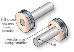
For calculations where a load will be moved during the cylinder’s return stroke, the cross-sectional area of the piston rod must be subtracted from the piston surface area. This is known as the annular area. The previous example used the full-bore area, but if you are moving a load on the return stroke, or using a cylinder with a rod at both ends, then the annular area must be used to calculate the usable piston area. (Rodless cylinders, however, have the full-bore area available on both faces of the piston, which eliminates the annular area.)
Know the Actual Operating Pressure
Although a compressor may produce a specified pressure, the pressure at the pneumatic cylinder can be much lower due to flow restrictions in compressed air lines and air consumption by other devices in the air-supply network. An air system that runs at 100 psi may drop to 80 psi or less during peak air-usage times of the working day.
Know the True Load
Unless you are lifting a load vertically, it can be somewhat difficult to determine the true load because of external friction. Even if a load is lifted vertically, if it is guided in any way, there will be additional friction. Calculating the force loss due to sliding friction must include friction factor:
Ff = Fp × fc,
where Ff = friction force, lb; Fp = force perpendicular to the sliding surface, lb; and fc = the coefficient of friction.
If the sliding surface is level, the perpendicular force is the object’s weight. If the sliding surface is inclined, the perpendicular force is the product of the cosine of the incline angle and the object’s weight.
Extensive information is available that documents coefficients of friction for various materials, but small variances in this number can make large differences in the required force. If you are sizing a cylinder for an existing application, try to physically measure the required force. If the application is new, do as much physical experimenting as possible to verify any calculated numbers you use.
After summing all the forces, the remaining (net) force is what causes motion. Acceleration of the load will be equal to the net force divided by the total mass being moved,
Fn = m × a
Unfortunately, it’s usually not this simple. Coefficient of friction often changes with speed. Furthermore, if net force is low, the pneumatic cylinder may exhibit stick-slip operation, sometimes called stiction. Stiction occurs when force from pressure is great enough to overcome static friction and begin moving the cylinder’s piston. Once the piston starts moving, dynamic friction comes into play. If static friction exceeds dynamic friction, the piston may suddenly stop when moving at very low speed because static friction has taken over.
As pressure builds, the piston again overcomes static friction force, and the piston lurches ahead. This start-stop motion can occur repeatedly and rapidly, resulting in a condition sometimes called “chatter.” Correcting the condition requires redesigning some aspect of the assembly, such as higher pressure or a larger bore. If these solutions are not possible, then seal and bearing materials with a lower coefficient of friction or additional lubrication may be called for.
Ensure Adequate Piping
The compressed air must reach the pneumatic cylinder’s piston quickly to build the pressure that will produce the force to move the load. Lines sized too small and with too many bends, turns, and restrictions will restrict airflow, causing sluggish operation and low force or torque from the actuator. Sizing lines and components too large will increase the volume of air that must be pressurized, increasing system response time.
A helpful analogy is that one person may be able to push a car at 1 mph, and two people may be able to push it at 2 mph. But 100 people cannot push a car at 100 mph. The reason they can’t is because they reach their terminal velocity. Although the 100 people have more than enough strength to push the car, they can’t move more than their own maximum (terminal) speed.
Compressed air is subject to the same limitations. If air can’t be delivered through the system quickly enough, then the pressure (force) at the cylinder will not reach that required to move the load. This potential problem is a result of inadequately sized components or an unbalanced system, not just too small a cylinder.
READ MORE: Why Tubing is Better Than Piping for Carrying Fluids
Consider the Angles
If the air cylinder in an application deals with linkages or has a force transfer angle or other pivoting member, allow for force losses in those angles. The force actually transmitted to the system is equal to the net force multiplied by the sine of the transfer angle:
Ft = Fn × sinθ
where Ft= force applied to the load, Fn = net force, and θ = the transfer angle.
The force absorbed by the pivot is equal to the net force multiplied by the cosine of the transfer angle:
Ft = Fn × cosθ
When the transfer angle is greater than 135° or less than 45°, more cylinder force is acting against the pivot than is being transmitted to the application. Transfer angles greater than 150° and less than 30° transfer less than half the cylinder force to the application, so they should be avoided. In these cases, a different mechanical arrangement or a rotary actuator could be used.
Plan for the Future
Specifying cylinders with nothing in reserve does not allow any leeway for future modifications to the application. Designing applications with some capacity held in reserve can allow for continued operation when a machine has been in service for a significant time (which may have increased friction) or when slight increases in product requirements or unforeseen force losses occur. For example, new pneumatic equipment installed in the facility may affect the available air pressure at your application. You can always add a regulator to reduce the pressure and output force, but it is much more difficult to increase force.
Account for Kinetic Energy
The load is moving, but what will stop it? Cylinders have some ability to absorb kinetic energy, but their primary purpose is to convert pressure to linear force. Installing a shock absorber can transform a potentially destructive moving mass into a good application.
Be Sure to Test
Trying to size a pneumatic cylinder mathematically to an application without any testing can be an expensive mistake. Once an application has been built, it can be quite costly to make changes to accommodate a larger-bore cylinder and may require redesigning an entire machine to accommodate additional space that may be required. If it turns out that more force or a different shape of cylinder is required, a tandem cylinder may provide a solution. Tandem cylinders have two pistons mounted to a common rod, so it provides greater force from a small bore, but at the expense of a longer length.
Information for this article was excerpted from material by Numatics Inc., Mt. Pleasant, Tenn.; Clippard Industrial Laboratory, Cincinnati; Peninsular Inc., Roseville, Mich.; and Bimba Mfg., University Park, Ill.


