Pneumatic Rotary Actuators: Back to School
This file type includes high resolution graphics and schematics when applicable.
Pneumatic rotary actuators are commonly used to convert compressed air pressure—in the form of a cylinder stroke—into an oscillating rotary motion. They are commonly used in industrial applications such as conveying, clamping, transferring parts, positioning, and controlling valves. Like other pneumatic components, they are durable, offer simplicity and high force for their size, and can operate in hazardous environments.
Many engineering colleges and universities have excellent fluid power curricula. However, rotary actuators often are not reviewed in the various machine applications. As a result, engineers may overlook rotary actuators as a design alternative. More often, common pneumatic cylinders are specified with a pivot arm to achieve rotary motion. Rotary actuators have the potential to improve and simplify applications greatly because they are self-contained and support loads due to the internal bearing sets. Additionally, there is no need to design and construct external pillow-block bearings. And, unlike piston rods exposed to airborne contaminants, rotary actuators can reduce maintenance issues in dirty environments.
This article provides a primer on common rotary actuators and a review for experienced engineers. The two most widely used designs of pneumatic rotary actuators are rack-and-pinion and vane. Both types come in single- and double-acting configurations. The single-acting version uses a spring or the load itself to return the actuator to a home position. This conserves compressed air usage by eliminating the need to consume air for the return stroke. Double-acting versions, however, provide greater control and can operate at higher cycling rates.
When selecting which type of rotary actuator is best for an application, the main design considerations are mechanical efficiency, package size, shaft options, max rotation, and cost. Beyond that, the designer must also consider characteristics, such as backlash, ability to stop a load, and ability to handle axial and radial loads on the shaft.
Rack-and-Pinion Designs
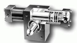
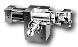
Rack-and-pinion actuators have a long piston with gear-rack teeth machined into one side that mesh with a pinion (small gear) that turns an output shaft. When the piston extends or retracts, its rack teeth rotate the pinion gear and output shaft. A double rack unit uses a pair of racks on opposite sides of the pinion, in effect, doubling the output torque of the unit.
Rack-and-pinion rotary actuators offer the widest ranges of torque and rotation. They provide excellent mechanical efficiency, often 90% to 95%. This makes them ideal for high-speed production applications and situations where low wear and long life are important. They have a boxy profile that simplifies mounting options. Additionally, hollow pinion gears offer flexibility, allowing the machine’s shaft to mount through the pinion gear of the actuator, thus eliminating a coupling.
One potential drawback with a rack-and-pinion design is backlash, which is caused by a very small gap between the gears. This is typically not an issue for most applications because the “play” is only about one degree. As the actuator operates through its life cycle, wear on the gears is common, which can cause the backlash to increase slightly over time. For applications that require precise positioning, a double-rack version can be used, which completely eliminates backlash by imposing a counter force on the pinion.
Unlike air cylinders, rack-and-pinion rotary actuators can accommodate side loads. The same roller-bearing assembly that supports the pinion can also support radial loads.
Vane Designs
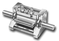
Vane actuators have a cylindrical chamber in which a vane is mounted on a central shaft. Air pressure applied on one side of the vane forces it to rotate until it reaches the end of its stroke. Alternatively, air pressure from the opposite side of the vane drives the shaft in the opposite direction until it reaches its end of stroke. In a single-vane design, rotary motion is typically limited to 280 deg. In a double-vane style, the motion is typically 90 or 100 deg., offering less rotational range with double the force of the single-vane construction.
Vane actuators offer the most compact package and are the first choice when space is limited. Because these actuators tend to be smaller, manufacturers don’t offer hollow shafts on standard units.
Compared to rack-and-pinion actuators, vane actuators have a limited rotation, typically up to 280 deg. maximum for a single vane model. They also have a limited torque range. The mechanical efficiency is fair, about 75% to 85%, mainly because of the friction of the vane seals, shaft bearings, and the very small amount of bypass leakage over the vane seals. It is virtually impossible to design a vane-type rotary actuator with bubble-tight vane seals.
Vane actuators do not exhibit backlash, so positioning is precise. The shaft uses small bushing-type bearings that can accommodate light loads only. Vane actuators are often used to clamp, transfer, or position light loads in medium-speed applications.
Vane seals do tend to wear a little faster, thus they do not have the cycle life of the rack-and-pinion design. On the other hand, vane actuators are the least expensive of the three types. So, this is a great choice in light- to medium-duty pneumatic applications.
They have minimal shock capability compared to other types. As such, external stops are typically required in higher speed applications. It’s really important to understand the kinetic energy in the system.
Guidelines for Specifying Rotary Actuators
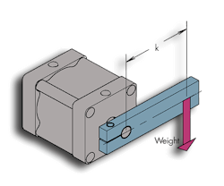
Stopping the load is more important than getting the load in motion. A key point to understand is that rotary actuators are typically sized based on their ability to stop a load rather than their ability to move the load. That’s because the kinetic energy of a rotating mass is exponential as the load moves further away from the rotation point. A component of the equation for mass moment of inertia is k2, meaning that the torsional load increases exponentially the farther away it is from the shaft.
For example, assume a 2-in. vane rotary actuator supplied with air at 100 psi has an output rating of 65 lb-in. of torque. In a typical application, this compact actuator can easily move a load over 270 deg. quickly. However, stopping the load by allowing the internal vane to strike the stator produces an instant stop, very much like a hammer to a hard surface. Furthermore, gravity acting on off-center loads can greatly add to the rotational velocity of the actuator shaft.
Imagine a small child pushing an adult on a playground swing; the child has the ability to start moving an adult in a full swing, but it would take many large adults to stop the swinging person in a short distance. Similarly, once the actuator gets to the end of the stroke, we must consider the kinetic energy absorption ability of the actuator.
In high-speed and load applications, the critical specification is not output torque but, rather, kinetic energy. It is common to learn that an application requires a larger actuator because the larger unit will have more capacity to stop a load. If the designer sizes the actuator based on torque output alone—on starting the load—then external stops will likely be required to stop the load. Therefore, consider both the demand torque and the kinetic energy absorption rating.
All manufacturers of rotary actuators provide torque output and kinetic energy absorption ratings. Some units have optional pneumatic cushions and internal hydraulic shock absorbers, which greatly enhance the stopping ability of the actuator.
Let the rotary actuator carry the load. Many engineers don’t realize that rotary actuators can support a load because they have bearing sets in them. This can be compared to linear slides, in which a pneumatic cylinder is coupled to a housing containing four recirculating ball bushings, a couple of shafts, and a tool plate. This actuator can now support a load. But rotary actuators already have the bearings in them, so the designer does not need to integrate bearings into the design. This is especially true of rack-and-pinion actuators, which utilize large roller bearings.
Take advantage of built-in stroke adjustment. With many models, options are available to adjust the rotational angle of travel. Most manufacturers provide adjustable stops as an option to provide an additional level of control over the application. This feature greatly simplifies setup time over setting external stops manually.
Sizing Considerations
The next step after selecting the type of pneumatic rotary actuator best suited for an application is to select an appropriate size. As already discussed, the three main design criteria are: torque output, kinetic energy absorption, and bearing-load capacity.
Torque output—Check manufacturers’ data sheets or catalog specifications for the particular actuator’s torque output. Select an actuator with enough power to accelerate the load from resting to the desired speed.
Remember, though, that losses due to friction in the actuator will always be present. If theoretical output torques are provided, allow an additional 10% to 15% for frictional losses for actual output torque. In rack-and-pinion units, this friction is caused by separation forces of the rack and pinion as well as seal friction. In vane actuators, seal friction exists, as well as a slight bypass leakage over the vane seals.
Many manufacturers provide this information in their specifications, providing actual output torque values that already account for inefficiencies. For example, a rack-and-pinion actuator may be 90% efficient. If actual output torque values are provided, the designer does not need to do the math; just be aware that the output specification factors in the frictional losses (efficiency).
Kinetic energy absorption—It is crucial to evaluate the kinetic energy absorption rating. Typically, designers find that even though a small actuator packs enough power to accelerate a load within a prescribed time period, a larger actuator is usually needed to stop the load reliably. If the kinetic energy requirement drives a much larger unit and becomes more costly, then the designer may make the decision to specify a small rotary actuator and stop the load externally. It’s more design work, but when very high loads and moments are involved, it will usually be less costly to design external stops than to specify a much larger actuator.
Load handling—Finally, evaluate the radial load on the output shaft. It will take some math to calculate the load, which is greatly affected by the distance of the load from the shaft. Manufacturers provide tables for the capacity of load handling based on the bearings and gear trains. If a load-handling requirement exists—especially a heavy load—size the rotary actuator based on its ability to hold the load. Again, this may require a larger actuator, as the bearing size is based on the size of the gear.
Bill Service is marketing manager, North America, at Parker Hannifin’s Pneumatic Div., Richland, Mich. For more information, call (269) 629-5000, or visit www.parker.com/pneumatic.
This file type includes high resolution graphics and schematics when applicable.
