Checklist for Matching Air Cylinders to Load Requirements
When applications involve linear motion, high speed, and moderate loads, many designers select air cylinders to provide the actuation. Compressed air is available as a utility at almost every industrial facility, and economical air cylinders can be obtained from a large number of manufacturers. One of the most fundamental fluid power components, cylinders have evolved into an almost endless array of configurations, sizes, and special designs. Their versatility not only makes more-innovative designs possible, but makes a reality of many linear applications that would not be practical or possible without cylinders.
Cylinders are simple devices, and calculating their theoretical force output is fairly straightforward. But sizing a cylinder properly for a real-world application can be much more complex. Undersizing, for instance, is a common mistake; resulting in sluggish performance and cycling problems in automated equipment. However, by following a few simple guidelines, engineers and designers can quickly learn how to determine the right cylinder to fit their specific needs.
1. Calculate the force. The theoretical force output of a cylinder is the product of the air pressure applied and usable piston area exposed to it,
F = P × A,
where:
F is force in lb,
P is supply pressure in psi, and
A is piston area in in.2
For example, a cylinder with a 11⁄2-in. bore supplied with 80-psi air would generate:
F = 80 π (1.5)2 / 4
F = 141 lb.
Also note that the formula calculates the theoretical force output. Several factors can and will lower it in a real application. Keep the following issues in mind whenever you size a cylinder.
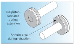
2. Use the annular area for calculations if applicable. The example above used the full bore area, but if you are moving a load on the return stroke, or using a double-rod cylinder, then the rod area must be subtracted from the full-bore area to calculate the usable piston area. (Note that for a rodless pneumatic cylinder, the full bore area is available on both faces of the piston.)
3. Know the actual operating pressure. Although a compressor may produce a given pressure, the pressure the cylinder actually sees in operation can be much lower due to air consumption by other equipment or restrictions in the air-supply network. An air system that runs at 100 psi may drop to 80 psi or less during peak air-usage times of the working day.
4. Allow for internal friction. A cylinder will never reach its theoretical force output due to its internal friction. This friction is produced by seals, bushings, and other load-support items such as wear bands. Allow 5- to 10-psi additional input pressure to overcome internal friction, depending on the type of seal design and cylinder bore. Cylinders with side load, misalignment, or specialty features will have even higher internal friction. Remember that a cylinder is a device to convert pressure to linear force. Considerable side loads and bending moments should be avoided or accommodated separately.
5. Know the true load. Unless you are lifting a load vertically, it can be somewhat difficult to determine the true load because of external friction. (Even in a vertical lift, if the load is guided in any way, there will be additional friction.) Calculating the force loss due to sliding friction is complicated by the friction factor:
Ff = Fn× f, where:
Ff is friction force in lb
Fn is force normal to the sliding surface in lb, and
f is the coefficient of friction.
If the sliding surface is level, the normal force is the object’s weight. If the sliding surface is inclined, the normal force is the product of the cosine of the incline angle and the object’s weight.
There are general tables available that document coefficients of friction for various materials, but small variances in this number can make large differences in the required force. If you are sizing a cylinder for an existing application, try to physically measure the required force. If the application is new, do as much physical experimenting as possible to prove any calculated numbers you use.
6. Include speed requirements in the equation. After summing all the forces, it is the excess force that causes movement. The acceleration will be equal to the excess force divided by the total mass being moved,
a = (Fe) (gc)/m, where:
a is acceleration in in./sec2
Fe is excess force in lbf
gc is the gravitational constant 386.1 lbm-in./lbf-sec2, and
m is total mass (including the cylinder’s piston/rod assembly) in lbm.
Keep in mind that the air must get to the piston quickly to build the pressure that will produce the force to cause the acceleration. Remember, one man can push a car at 1 mph, and two men may be able to push a car at 2 mph, but 100 men cannot push a car at 100 mph. The reason they cannot is that they reach their terminal velocity. Although the men have the strength to push the car, they cannot move at the target speed. Compressed air is subject to the same limitations. If the air cannot be delivered through the system quickly enough, then the pressure — and force — at the cylinder will drop, and the load will not accelerate. This potential problem is a result of inadequately sized components or an unbalanced system, not just the cylinder.
8. Allow for the future. Designing cylinders “right to the edge” does not allow any leeway for the future. It is a good idea to leave openings for slight increases in product requirements or unforeseen force losses. For example, new pneumatic equipment installed in the facility may affect the available air pressure at your application. You can always add a regulator to reduce the pressure and output force, but it is much more difficult to add force.
9. Remember kinetic energy. The mass is moving. What will stop it? Do not forget the kinetic energy associated with the moving load. Cylinders have some ability to absorb kinetic energy, but their primary purpose is to convert pressure to linear force. Installing a shock absorber can transform a potentially destructive moving mass into a good application.
10. Be sure to test. Trying to size a cylinder mathematically to an application without any testing can be an expensive mistake. Once an application has been built, it can be very costly to make changes to accommodate a larger-bore cylinder. Sometimes the entire application or machine must be redesigned to allow for the required additional space. (Tandem cylinders can be used to increase force and only extend the cylinder width, but they are less efficient than using a cylinder with a larger bore.) Unless you have strict time constraints or air-consumption limitations, it is probably a good idea to oversize the cylinder.
Joe Malloy is chief engineer, Numatics Actuator, Franklin, Tenn. Click here for more information..
