Behavior of Cylinder Pressures in Motion Control
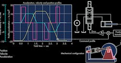
The instantaneous pressures in the two ends of the actuator are interesting because they reveal peculiarities in the hydraulic servo system. To demonstrate the characteristics of a motion-control system, we will examine test results of a valve-controlled cylinder in a closed-loop, positional servomechanism (Fig. l).
The mechanism was designed for special electrohydraulic motion-control training programs using a cylinder with a 2-in. bore, 1 3/8-in. rod diameter, and 6-in. stroke, and a magnetostrictive linear displacement transducer for position feedback. The load is a 4-in. thick, 16-in. diameter, 250-lb flywheel. The flywheel produces an equivalent mass at the cylinder rod of approximately 1,500 lb when the 3.5-in. torque arms are perpendicular to the cylinder rod. The cylinder is connected to the flywheel in a cranking fashion, as shown at the lower-right of Fig. l. This combination produces a natural frequency of about 20 Hz. The constraints of the cranking mechanism limit the maximum stroke of the cylinder to just under the full 6 in.
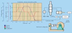
Cylinder motion is controlled using a PC equipped with a general-purpose data interface with analog input and output. Acceleration, velocity, and position profiles are also shown in Fig. l. The motion-control profile was synthesized on the PC using the Profile Synthesizer module in the VCCM repertoire of computer programs. Only proportional control was used; no integral or derivative control was used.
1. Position, velocity, and acceleration profiles, left, are used to command a servomechanism though its entire cycle. A schematic representation of system is shown at upper right, and a simplified drawing of the mechanical configuration is shown at lower right. An initial dwell (velocity is zero) of 0.6 sec. occurs at the beginning of the profile. It is followed by a 0.28-sec. period of constant acceleration at 18 in./sec.2. Next comes a 0.5-sec. period of constant speed at 5.1 in./sec (covering about 2.5 in. of cylinder travel). The end of extension is marked by a 0.28-sec. deceleration, followed by a 0.5-sec. dwell. The retraction portion of the cycle is symmetrical; however, it terminates with a final dwell of about 0.5 sec.
Even though Fig. 1 shows three profiles, only the position profile serves as the command. The computer serves merely as an arbitrary function generator. It holds the data that describes the point-to-point values of the position command profile and provides a “moving target” to stream the profile data to the feedback (servo) loop. The command profile is nothing more than a motion plan, giving the servo something to follow. However, the actual motion of the cylinder will be merely a close approximation of the command profile.
The PC logs and keeps track not only of where the cylinder should be at every moment, but also where it actually is, its actual velocity, and the instantaneous values of cap- and rod-end pressures. How closely the cylinder’s actual motion matches the motion command is the subject of this study. The difference between command and feedback is the error signal, which is the numerical difference between the command profile and the feedback signal at every instant in time.
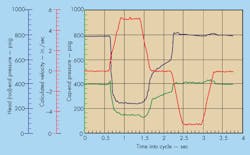
Figure 2 superimposes the rod- and cap-end pressures in the cycling cylinder along with the measured velocity, which is added for timing purposes. We can correlate the conditions of acceleration, constant speed, deceleration, extension, retraction, etc. with the pressure variations. Of course, the command profile is the same as that in Fig. 1.
The first point of interest are those periods when the cylinder is at rest, and the cylinder pressures are not zero. The profile, recall, begins with a ½-sec dwell, which is the first 0.6 sec. or so of the traces in Fig. 2. The pressures in that interval are about 790 and 395 psi on the rod and cap ends, respectively. Their ratio conforms closely to the cylinder area ratio, which is about 1.9.
2. Color-coded plots show head- and cap-end pressures as cylinder strokes through cycle.
Pressure Metering Characteristics
Conventional wisdom would have the cap-end pressure rising and the rod-end pressure falling in order to accelerate while extending. However, that is not the case. Acceleration to extend occurs at about 0.7 sec. into the cycle, and a very short duration occurs where the cap-end pressure rises, but the rod-end pressure is falling everywhere during the first stages of acceleration to extend. This is a fact of life in the hydraulic servo system. The two pressures are non-zero because of the pressure metering characteristics of the control valve.
The cylinder stops, but not because the flow is shut off nor because the valve centers. It stops because the forces are brought into equilibrium in accordance with Newton’s Laws, and the condition of equilibrium can be realized only by looking at the pressure metering characteristics of the valve. Furthermore, the pressure metering of the valve exists because this valve—as with all spool valves—exhibits internal leakage. In the null zone of the valve—the region where the spool is nearly centered—pressure metering is more important to the stopping condition than it is flow metering.
After the valve opens and the cylinder attains some velocity, the pressures become a complex function of the supply pressure, the load on the cylinder, the cylinder areas, and the valve ratio. Interestingly, they are not dependent on the speed of propulsion nor the valve coefficient.
The period between about 0.9 and 1.5 sec. correlates closely with the time in which the speed is essentially constant. The rod- and cap-end pressures are, respectively, about 250 and 160 psig.
When propelling in reverse at constant speed, the time between 2.5 and 3 sec. applies, and the two pressures are about 800 and 400 psig, respectively. Therefore, it should be clear that the pressures between holding and propelling are quite different because they are governed by different features of the valve.
This can lead to some problems in critical applications, say, when grinding a lens. This situation requires large, sudden changes in the two pressures as the cylinder goes from extending to retracting. The large pressure change can result in a slightly jerky reversal, putting a flaw in the lens. The difference in pressures can also create problems when propelling at very low speeds, especially if considerable breakaway friction exists. The need to have large pressure variations can cause a jerky, start-stop motion.


