Have You Considered Air-Over-Oil Circuits?
Because air cylinders produce fast, repeatable motion, achieve high cycling rates, and don’t generate substantial heat, they are well suited to factory automation systems. However, air is compressible—which is an advantage in many applications, but complicates closed-loop motion control. A solution often overlooked is to incorporate a closed hydraulic circuit to regulate speed and provide load holding for the otherwise all-pneumatic system.
Air-over-oil systems offer a cost-effective alternative for many closed-loop speed control applications by combining the convenience of readily available compressed air for power with hydraulics to control motion. These unconventional systems are well suited to low-power systems where smooth speed control, rigidity, or synchronized motion are needed.
Most components needed for air/oil systems are standard hydraulic and pneumatic products—but no hydraulic pump is needed. When greater force is needed, a pneumatic pressure intensifier can be used to boost air pressure from roughly 100 psi to several hundred psi. Components unique to air/oil circuits can be manufactured in-house from standard products or purchased from a variety of sources.
For example, and air/oil tank can easily be constructed from a standard air cylinder by removing the piston and rod and replacing the rod-end cap with a second blank cap end. Some manufacturers offer self-contained, air-powered cylinders with built-in oil cylinders and reservoirs. Some units have two-speed capabilities as well as stop and hold options.
Coupling low-pressure hydraulic cylinders with air-over-oil tanks is a common way to create an air-over-oil system. These tanks hold more than enough oil to stroke the cylinder one way. Having an air valve connected to the air-over-oil tanks forces oil from the tanks into the cylinder. Add flow controls and stop valves to the oil lines to give smooth accurate cylinder control. Air-over-oil tanks do not intensify the oil, no matter the tank diameter or length. The amount of air pressure supplied is the highest possible oil pressure available. But, again, if greater force is needed, a pneumatic pressure booster (intensifier) can be installed upstream of the compressed air inlet.
Tandem cylinders can also control oil and air power. The single-rod cylinder of the tandem runs on air, whereas the double-rod cylinder is full of oil. Because volume is equal in both ends of the double-rod cylinder, oil flows from end to end through flow controls or shut off valves for accurate speed and stopping control.
When designing with air-over-oil systems, take care sizing the oil lines. Most air-oil circuits operate at 100 psi or less, so any pressure drop in the circuit can substantially reduce the force applied by the cylinder. If oil lines are undersized, cylinder movement will be very slow. Size most air-over-oil circuit oil lines for velocity of about 2 to 4 ft/sec. This low speed requires large lines and valves, which are necessary if average travel speed with maximum force is important.
Bleeding of air from the oil chambers can present another common problem with air-over-oil circuits. Any trapped air in the oil will make cylinder operation spongy. This compressibility makes accurate mid-stroke stopping and smooth speed control difficult to achieve. When using an air-over-oil tank system, it is best to mount the tanks higher than the cylinder they feed. All lines between the cylinder and the tanks should slope up toward the tanks. Also, if possible, let the cylinders make full strokes to purge the air. Incorporate a means for equalizing tank level in the design when a dual-tank system is used.
The cylinder seals must be as leak-free and provide low friction. Any leakage past the seals can cause tank overflow, oil misting, and loss of control. The following examples can be used to provide low power with smooth control rather than oil hydraulics.
Click here to learn about intensifiers of use in air-over-oil circuits that also require short, high-force work strokes.
Basic Air-Over-Oil Circuits
Figure 1 shows a single tank air-over-oil system with an air valve piped to an air-over-oil tank. As shown, compressed air will flow into the top of the tank and push hydraulic oil into the rod end of the cylinder, causing the rod to retract. The oil flows through the check valve, bypassing the flow-control orifice, so the cylinder retracts quickly.
1. As shown, this single tank air-over-oil system will retract at full speed. Shifting the valve routes hydraulic fluid through the check valve and orifice to provide speed control during extension.
Shifting the directional valve routes compressed air directly into the cap end of the cylinder. As the piston rod extends, oil is forced out the rod end of the cylinder and through the flow-control orifice, which provides a controlled extend speed. If the load should reverse, the flow-control orifice prevents the rod from extending faster than the flow control allows. If force requirements keep changing while the cylinder is moving, speed will change very little as long as the cylinder has enough force.
Air leaking past the piston seal can be an issue in a single-tank air-oil circuit. Any air mixed with the oil can cause erratic movement and compromise control. This circuit is good for replacing a straight air cylinder that is moving a large load. When load force on the extend stroke varies, a straight air cylinder may stop or lunge uncontrollably. With oil in the rod end of the cylinder, movement will be smooth. Even if the cylinder stops, it will not lunge when it again starts to extend.
Notice the baffles in the air-oil tank. The top baffle keeps incoming air from shooting into the oil, which would promote aeration. The bottom baffle helps prevent air from being drawn into the cylinder as the tank level lowers.
Sight gauges are also necessary to monitor oil level on the air-oil tank. Purchased air tanks usually come with baffles, sight gauges, and a fill port. Some purchased air-over-oil tanks feature air cylinder tubing with two cylinder caps held in place with tie rods. Air-over-oil tanks should be sized to run approximately 75% full for optimum performance.
Figure 2 shows a double tank system. Two tanks eliminate the issue problem caused by leaking cylinder seals. They also allow accurate speed or stop control in both directions of travel. A twin-tank system is more expensive, and it may reduce maximum cylinder speed slightly. When using two oil tanks, always put a line with an equalizing valve between the tanks. This line should be below the lowest tank oil level to allow easy adjustment of tank oil level when cylinder seals bypass.
2. The double-tank air-over-oil system provides speed control for both extension and retraction.
CAUTION: Never fill a tank to capacity when the cylinder is stroked away from it. Otherwise, the oil will overflow in the tank from excess fluid in the cylinder returning to the tank.
Install a solenoid or pilot-operated shutoff valve in the oil lines to the cylinder for accurate control. A shutoff valve lets you precisely position and hold the cylinder for long periods. Because oil can be considered incompressible at these relatively low pressures, a cylinder will not move even if outside forces push against it. If excessive outside force is possible, install a relief circuit to protect the cylinder and machine structure.
Tandem Cylinders in Air-over-Oil Circuits.
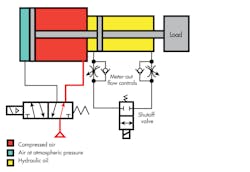
Figure 3 shows a tandem cylinder piped for speed control and mid-stroke stopping. A tandem cylinder unit provides the same results as an air-over-oil tank system. The air valve piped to the single-rod cylinder gives directional control. Install meter-out flow controls and a shut-off valve in the line between ports on the double-rod cylinder. The double-rod end cylinder is completely full of oil and sealed against leakage. However, a small reservoir attached to the transfer line—with a check valve between it and the cylinder port—lets oil enter the cylinder when needed.
3. Using a tandem cylinder provides a simpler means of speed control in both directions but requires more space at the actuator because at the tandem is larger than a standard double-acting cylinder.
This tandem cylinder arrangement operates smoothly and gives accurate mid-stroke stopping control. A tandem cylinder costs about the same as a dual-tank system. However, the size of the tandem cylinder is about twice that of the conventional cylinder. Also, long-stroke tandem cylinders can be difficult to mount and maintain. Normal piston seal leakage normally is not an issue, but rod seal leaks can let oil out or air in, creating the potential for external leaks and spongy cylinder movement.
Figure 4 shows a large-bore, high-force air cylinder with a small-diameter hydraulic cylinder in tandem with it. An unmatched tandem cylinder has ample oil for smooth control and precise positioning. Unmatched tandem cylinders offer two big advantages: less cost and lower oil flow.
4. An unmatched tandem cylinder can be less expensive and smaller than a standard tandem cylinder, but the different cylinder volumes makes pressure of flow intensification an issue.
When specifying unmatched tandem cylinders, make sure the piston rod sizes are compatible between the air and oil cylinders. Rod size usually dictates the smallest bore hydraulic cylinder possible. Also, check for excessive pressure in the oil cylinder that could damage it and other components. The higher oil pressure comes from intensification due to different bore sizes. Also, a vertically mounted cylinder with a heavy load adds load-induced pressure to intensification, possibly damaging components rated for air or low-pressure hydraulic service.
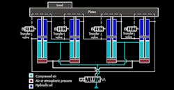
Figure 5 shows an accurate way of synchronizing two or more tandem air cylinders with fluid power. Four tandem cylinders are hooked to one platen, which will stay level throughout the stroke. Force from all four cylinders is available to move the load, regardless of its position.
5. Two or more tandem cylinders can be a convenient way of achieving synchronized motion. However, cylinders should be fully extended or retracted after each cycle to prevent accumulated positioning error.
Notice the transfer valves between the tandem cylinder’s cross port lines. Always return a fluid-type synchronizing circuit to a positive home position often, preferably after every cycle. When the air cylinders return the platen to home position, the transfer valves open to let the cylinders to re-synchronize. Doing this after each cycle eliminates any cumulative position error from seal leakage.
When using unmatched tandem cylinders in a synchronizing circuit, check for overpressure from intensification and load-induced pressure as already mentioned. Placing a heavy load over one cylinder provides pressure intensification from the other actuators. All other cylinders will transfer their excess energy through the oil lines to the loaded cylinder. The loaded cylinder could then push with four times its normal force. One-fourth of this force would be from its own air cylinder, whereas three times more force would come from energy transfer. This could overpressurize the cylinders or valves, causing failure.
Figure 6 shows opposing tandem cylinders. This is a specific arrange to make the piston rods meet midway between the cylinders. One application for this setup would be position different size parts for drilling or punching a center hole in the workpiece.
6. Opposed-mounted tandem cylinders extend equally, and their piston rods meet midway, which provides a simple solution for centering different-sized workpieces.
This discussion is an update from Fluid Power Circuits Explained, originally authored by Bud Trinkel.
