There are five design criteria for choosing the cylinder bore:
- Stall force requirements must be met or exceeded, which applies to presses and similar machines.
- The rod diameter must be large enough to avoid buckling based on the rod length and the load.
- The natural frequency must be 2 to 100 times higher than the frequency of acceleration, depending on required following error, the damping factor, and control algorithm used.
- Enough force must be available to accelerate the load in both the extend and retract directions.
- Cavitation (formation of air bubbles in the fluid) must be prevented while decelerating. Usually, this only happens when extending a heavy load, then trying to decelerate quickly, known as an over-running load.
The first two criteria are pretty straightforward. Criteria One is easy to calculate, and Criteria Two requires looking up specifications from the cylinder manufacturer to check if the rod diameter is large enough. Criteria Three, however, depends on the control algorithm used by the electronic control. This is where a hydraulic motion controller can pay for itself. Simple PLC-type control may use only a proportional gain. The physical system’s natural frequency will need to be very high to obtain a suitable response. Unfortunately, increasing the natural frequency by a factor of two requires increasing the cylinder bore by about the same amount but increases the flow requirement by a factor of four. This can be expensive. Hydraulic motion controllers with a PID and velocity plus acceleration feed forwards (FFs), require a natural frequency of about four times the frequency of acceleration. The best hydraulic servo controllers may allow the natural frequency to be reduced to about two times the frequency of acceleration. Being able to use smaller-diameter cylinders for the same application saves a lot of money, as long as the other criteria above are met.
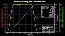
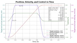
This graph shows where in the motion profile the key velocities and forces occur. These four values are needed for the two VCCM equations to calculate the area of the powered end of the cylinder, Ape.
Criteria Four is difficult to calculate. Typically, maximum force is required when accelerating the load. Assuming the motion controller uses S-curves while ramping, the peak acceleration occurs at half the maximum steady-state velocity. This means that multiplying the supply pressure by the area of the piston, then dividing by the mass, will not provide a valid answer. The reason is that pressure losses occur as the oil flows through the valve to the pushing side of the piston. Also, backpressure acts on the exhaust side of the piston to push oil out of the cylinder. This means the pressure on the pushing side and exhausting side of the piston are unknown without doing some math. The differential force can be calculated and used to calculate the potential acceleration at half of the required steady-state velocity.
Criteria Five must be met to avoid cavitation while decelerating. Cavitation from an over-running load is common when attempting to decelerate loads where the rod is pointing down, or must be decelerated quickly. Cavitation usually is only a problem on the cap end of the cylinder. Calculating this requires knowing the braking force required to decelerate from the maximum steady-state velocity without causing pressure in the cap end of the cylinder to go to zero.
Calculating the Natural Frequency
A couple different formulas are used for calculating the natural frequency. The one I prefer is:
The hard part is keeping the units correct. The natural frequency has units of radians per second. To convert from radians per second to Hertz, divide by 2π.
The natural frequency, in Hz, must be compared to the frequency of acceleration. The cylinder bore must be increased until the natural frequency is four times the frequency of acceleration. This is based on the assumption that a PID algorithm will be used with feed forwards. I use a computer program that will index through a table of cylinder sizes from smallest to largest until the natural frequency requirement is met.
The VCCM equation can also be used to calculate the cylinder bore and valve size. Two VCCM equations are required to calculate the cylinder bore and the valve size. The VCCM equation is:
However, this equation assumes the valve is fully open. It is best to leave some head room, so I multiply Kvpl by 0.9. This assumes that the piston reaches the maximum required steady-state velocity when the valve is 90% open, instead of 100% open:
The second equation is the same as the first with a couple of modifications. The velocity is half the maximum required steady-state velocity, where the peak acceleration occurs. At half velocity (peak acceleration), the valve is open 60%. The 60% value comes from the fact that at a velocity of half the maximum steady state, the valve should be open about 45% due to the velocity feed forward. The remaining 15% is an estimate of the acceleration feed forward at peak acceleration. The second VCCM equation uses the frictional force plus the force required to accelerate the load at peak acceleration:
We now have two equations and two unknowns, the flow constant for the powered land of the valve, Kvpl, and the area of the power end of the cylinder, Ape. Actually, there are four unknowns. The valve port ratio and the cylinder ratio are unknown, too. Surprisingly, the solution for the area if the powered end, Ape, does not depend on the valve or cylinder ratios. Solving for the two unknowns requires a little algebra. The solution for the area of the powered end is relatively easy, but the solution for the flow constant of the powered land is not. Fortunately, the solution for the area of the powered end does not depend on the cylinder ratios or the ratio of the flow constants for the A and B ports. The formula for the Ape is:
This assumes that v1 is half of v2.
If the cylinder’s piston rod is pointing down, as in a hydraulic press, the area of the piston’s powered end may be negative. This happens when gravity alone is enough to make the rod extend. In this case, the cylinder bore will be determined by using the same formulas, but using the values for retracting.
The formula for the valve flow constant is extremely complicated, so we’ll ignore it for now. The reason is that the formula for the valve size assumes the solution for the area of the powered end is the value that will be used in calculating the valve flow constant. The formula is accurate, but try finding a cylinder with exactly that calculated piston area, Ape! So, the next step is to search through a table of standard cylinder sizes to find the next biggest diameter that meets the area requirements.
I usually find the area of the cap-end side of the piston first. Once I find that, there are two choices for the rod diameter. The standard rod size results in a rod-end area of about 70% of the cap-end side. There is also a rod diameter option for which the area on the rod end is 50% of the cap end. I usually start with the standard-size rod diameter. Now the cylinder ratio is known. The valve ratio is assumed to be one at this point.
The next step is to calculate the valve flow constant using the formula for the Kvpl equation using the updated, rounded-up area of the powered end:
Next, the valve size can be calculated. Assuming the valve is rated at 70 bar, the pressure drop across each land will be 35 bar, so:
The solution should try both the standard ratio and 2:1 ratio cylinder sizes and the standard symmetrical and asymmetrical valve spools. Sometimes an asymmetrical spool will work much better with systems that might cavitate while decelerating. Using a cylinder with a 2:1 piston area ratio is better if the cylinder rod is pushing up.
The design must now be checked for cavitation to meet Criteria Five. Calculating whether the cylinder and load will cavitate will be covered in next month’s “Motion Control”.
Peter Nachtwey is president of Delta Computer Systems Inc. and has more than 35 years of experience developing industrial control systems for hydraulic, electric, and pneumatic applications. In addition to leading Delta’s engineering and R&D programs, he contributes widely to the mathematical understanding of control theory, especially in fluid power systems.


