Hydraulic flange fundamentals
Flange connections are used in the most demanding mobile equipment applications because they:
• are well suited for high pressure, shock and vibration, especially in larger sizes,
• allow easy connection between hose and tube/pipe where flexibility is needed, without adding adapters,
• allow for easy connection between rigid lines (tube-to-tube or pipe-to-pipe) and aid in installation and repair,
• maintain a high resistance to loosening in severe hydraulic service,
• can be assembled with reasonable assembly torques, even in larger sizes, and
• can be assembled in close quarters where wrench swing clearance would be problematic.
Basic design
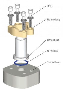
The 4-bolt flange port connection consists of four primary components: flange head, O-ring, flange clamp (captive or split) and four bolts. The port is simply a flow passage surrounded by four tapped holes that accept the clamping bolts. Typically, the flat-machined surface of the port compresses the O-ring contained in the groove of the flange head when the bolts are tightened. The bolts, placed through the flange clamp, squeeze on the flange head, compressing the O-ring in the groove leaving no leak path or possibility of O-ring extrusion, Figure 1.
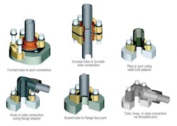
For pipe or tube connections, a flange head with a machined O-ring groove is typically welded or brazed on. An alternative is to place a flat face flange onto the end of the tube or pipe and use a bonded elastomeric seal plate as the seal between the two flat surfaces. This eliminates the need for welding or brazing.
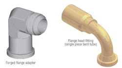
Hose connections can be achieved with a single-piece flange, Figure 2, that is crimped onto the end of the hose. Such flange adapters are used to adapt either tube or hose to a four-bolt flange connection. When using flange adapters, the pressure rating of the threaded end should be taken into consideration.
Types of flanges
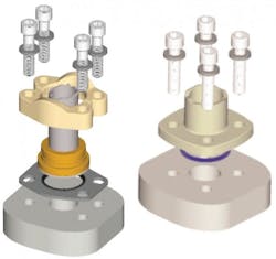
Two common industrial standard hydraulic flange connections and several specialized and proprietary types of hydraulic flanges are available. The most common is the ISO 6162 connection, Figure 3. ISO 6164, Figure 3, is a square bolt flange connection not commonly specified in North America.
This rectangular bolt-patterned design is available in two pressure classes: Code 61 — a series for up to 5000 psi (34.5 MPa) and Code 62 — a series for up to 6000 psi (41.4 MPa).
Note that the two pressure classification flanges are not interchangeable and have different bolt patterns. The ISO 6162 is considered the worldwide hydraulic flange standard, as it includes the North American Standard (i.e., SAE Code 61 and 62 or SAE J518) with UNC threads and the International standard with metric threads.
The second style is a four-bolt square (equally spaced) pattern flange connection in accordance with ISO 6164. Although the technology is identical, this flange connection, although common in Germany, generally is not used in North America.
There are other proprietary type flanges that are associated with some large OEMs.
Applications
The hydraulic flange connection was developed as a large-sized high-pressure connection. While large-sized threaded connections require a very high assembly torque to resist high pressures, flange port connections divide the assembly torque among multiple bolts, each of which requires much less torque. Large threaded connections also present assembly difficulties especially where wrench clearance is limited.
In fact, flange connections provide for zero-clearance assembly that enables easy connecting, disconnecting and maintenance of tube-to-tube, tube-to-hose and manifold connections. Infinite positioning is a “built-in” feature, in that the flange can be positioned at any angle. In addition, flange connections have the highest resistance to loosening, due to the clamping load distribution over the flange head. This makes flange connections an ideal choice for bent hose end connections that are subjected to very high lateral forces that tend to cause loosening.
For more information on hydraulic flanges and tube fittings, visit www.parker.com/tfd.
About the Author

Leaders relevant to this article:


