Hydraulic fan drives have caught on as the most effective way to cool diesel engines. A diesel’s operating efficiency (fuel consumption) and emissions output are closely related to operating temperature. A diesel consumes the least amount of fuel per horsepower produced within a relatively narrow band of temperatures. Likewise, a diesel puts out the least amount of emissions per horsepower within a similar temperature range. So operating the engine within the narrow range of temperatures where the two overlap derives the most power from a diesel engine while minimizing fuel consumption and emissions.
Traditional, belt-driven fans produce air flow that is dependent upon engine speed, not cooling demand. This means belt-driven fans usually deliver too high or too low an air flow, which not only causes wide fluctuations in engine temperature, but wastes power. Maximum power is lost when the engine (fan) runs at high speed, even though little cooling may be needed. Moreover, an idling engine may need very little air flow, but, again, the fan continues to run at an unnecessarily high speed. Unlike traditional systems, hydraulic fan drives operate with variable speed. This means air flow through the radiator can be closely matched to the cooling requirements of the engine.
Multiple benefits
In its simplest form, a hydraulic fan drive consists of a pump, pressure control valve, motor, sensors, electronic control and, of course, all the hydraulic fan drives also allow mounting the radiator in a location that may be more practical than adjacent to the engine. Placing the radiator in a location away from major sources of dirt and contamination means it will stay cleaner longer. Furthermore, fan direction can be reversed when accumulated debris needs to be blown out of the radiator. These characteristics improve cooling by keeping the radiator operating more efficiently. Furthermore, the radiator and fan can be mounted in a location that directs heat away from the vehicle, which can save additional energy by reducing the cooling load on the operator cabin.
A design to suit the application
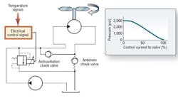
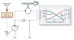
The simplest and least-expensive hydraulic fan drive uses a fixed displacement pump driving a fixed-displacement motor, with a pressure-control valve to regulate motor torque (fan speed). These systems react quickly and offer high repeatability to small speed trimming commands, typically using an inverse-acting proportional pressurecontrol valve. This setup ensures that the fan defaults to full speed if the controller loses power or some other malfunction occurs. With a conventional drive, a broken belt can cause the engine to overheat or shut down.
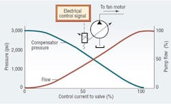
When high power is needed for cooling — typically 50 hp and greater — a system driven by a variable- displacement pump becomes more practical because its ability to produce virtually zero flow means even higher system efficiency. This, in turn, produces a quick payback on its higher initial cost. Some of these systems control fan speed directly by varying flow from the pump instead of controlling pressure. This type of pump control typically consists of a small pilot version of the inverse acting proportional valve to control the pump’s pressure compensator. The same controller can be used for either type of system because a proportional valve serves as the interface between the hydraulics and the electronic control. Furthermore, if a variable-displacement pump has overcenter (reverse-flow) capability, the fan can be reverse driven without having to use a directional valve.
Hydraulic fan controllers from High Country Tek (HCT) use discrete temperature thermistors. These are readily available from the automotive industry and are an inexpensive method of measuring temperature. The controllers can operate very well as stand-alone systems, making them easy to retrofit or upgrade existing systems, especially on older equipment that is being repowered or refurbished. However, they also readily interface with application status monitoring systems.
The latest generation of fan-system controllers for new-equipment designs is more reliable and easier to use by minimizing external connections and doing away with external sensors. Instead, they rely on the established J1939 communications BUS standard for the temperature data needed for the fan speed control. This BUS is also used to send system and controller status messages to in-cab instrument clusters to inform the operator in real time of operating conditions and if any action should be taken.
Taking control
Controllers from HCT operate transparently, are mechanically robust, and survive environmental extremes that exceed normal expectations for precise control electronics. They are available with CE compliance for compatibility with other electronic systems. The units are fully potted (encapsulated in a flame resisting resin), giving them a NEMA-4 or IP-67 sealing rating so they can be mounted in areas where cyclic heat, humidity, and debris are expected.
To ensure that controllers maintain integrity and continue to work as designed, the internal components have extended temperature operation. All the electrical connectors used are two-part polarized to aid with wiring harness assembly and to avoid misconnection during insertion, with the most advanced using a multi-pin automotive sealed variety. Complete controller operation can be observed through software on a PC, with all critical input and output functions and alarms indicated by external LEDs. All the external visual indicators are designed to be noncritical to controller operation in the event they suffer damage. Overall physical dimensions of the controllers are kept as small as possible to keep their footprint small to provide flexibility in choosing a mounting location.
Controller functionality may vary depending on what the application demands. The simplest is a three-channel temperature unit with just a fan-speed control. The most complex can address multiple fluid temperatures, offer fan reverse for radiator purge or de-icing, as well as auxiliary inputs and outputs that can interface with multiple external systems, such as air conditioning, other logic valves, and even extended monitoring functions.
All HCT fan controllers are programmable so that each model can be used in a wide range of application. Their straightforward graphical user interface uses passwords to protect critical OEM settings while allowing different levels of access authorization to be set. The characterization software allows the equipment manufacturer to quickly and successfully tailor the operation to the individual system needs by entering minimal data. Digital operation ensures high accuracy, repeatability, and safe operation of the system.
All controllers offer alarm indicator functions with several offering high current alarm outputs capable of interfacing with external audio or visual indicators that can alert the operator of a system or controller fault code. To improve prognostics in the system, The newest versions of the with J1939 interface offer DM1 diagnostic messaging, which can be used for predictive maintenance.
Gary Gotting is Vice President at High Country Tek, Nevada City, Calif. For more information on the High Country Tek range of hydraulic fan and other controllers, contact the author at (952) 681-2577 or visit www.highcountrytek.com.
About the Author

Leaders relevant to this article:


