Keep cool, save money
Much has been written highlighting the benefits of using hydraulic fan drives to provide on-demand cooling of diesel engines. Such benefits include:
- lower fuel consumption
- air flow based on cooling demand
- lower emissions
- engine temperature remains within optimum range
- greater portion of engine power available for work functions.
These benefits result from the hydraulic fan drawing less power than a belt-driven fan and from operating a diesel engine at its optimum temperature. Operating temperature has a two-fold effect on diesel engine performance. A diesel engine's power-to-fuel economy ratio peaks within a relatively narrow range of temperatures. Also, the output of emissions to power is lowest within another narrow range of temperatures. These two ratios overlap within an even narrower range. Therefore, engine temperature must be kept within this range for maximum efficiency and minimum-emissions.
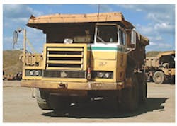
Retrofitting a Terex 50-ton Payhauler with a variable-speed hydraulic fan drive offers multiple benefits, including a return-on-investment of only 3 months.
Conventional cooling systems drive a fan according to engine speed, which has no correlation with cooling demand.
Powering the fan with a hydraulic system regulates air flow based on demand, rather than on engine speed.
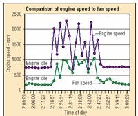
Plot of engine speed shows how fan speed automatically adjusts to cooling demand.
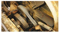
Conventional cooling systems use a belt to drive the fan from the engine's crankshaft pulley. Coolant temperature is controlled by a thermostat, which opens or closes over a wide range of temperatures. It responds after a high or low temperature limit has been reached and is slow to react. This causes coolant temperature to constantly drift between high and low extremes, rather than operate within a narrow range. In addition, thermostats regulate temperature by restricting water flow, which increases water-pump pressure. This backpressure not only can shorten life of the water pump, but also robs power from the engine. Second, because airflow produced by the fan depends on engine speed, there is no correlation between airflow requirement and airflow produced.
Fans are sometimes driven by an electric motor. But like a thermostat, a motor-driven fan constantly cycles on and off to allow coolant temperature to fluctuate over a wide range. Furthermore, electric motor-driven fans still rely on a thermostat to regulate coolant temperature.
A better way
Hydraulic fan drives (HFDs) have emerged as more-effective means of controlling coolant temperature. Instead of using a belt-or electric-motor-driven fan, the HFD uses a hydraulic pump, electrohydraulic pressure-control valve, and hydraulic motor to drive the fan. A critical element of the HFD is its electronic control, which regulates fan speed based on input from electronic sensors. These sensors monitor coolant and ambient air temperatures and other parameters to provide closed-loop temperature control within a narrow range.
Despite the many benefits of hydraulic fan drives, quantitative data supporting their merits have not been widely publicized. Therefore, a controlled test program was conducted to collect data for quantitative analysis of a hydraulic cooling system from High Country Tek, Nevada City, Calif. Tests were conducted using a Terex 50-ton Payhauler equipped with a Cummins 1710 (725 hp @ 1800 rpm) diesel engine at a quarry. Tests used the same driver, over the same route, and on consecutive days to ensure nearly identical test conditions. The vehicle was fitted with sensors to monitor engine-coolant temperature at multiple locations, ambient temperature, fuel flow, hydraulic fluid pressure, and other relevant parameters.
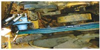
The retrofitted HFD consists of a fixed-displacement hydraulic pump driven from the flywheel sheave through a belt drive. This is where similarities with a conventional system end. Pressurized fluid from the pump flows through an electrohydraulic pressure-control valve to a fixed-displacement hydraulic motor. A hydraulic fan drive electronic control from High Country Tek processes inputs from electronic sensors and provides closed-loop pressure of the electrohydraulic valve. Normally, controlling flow regulates speed of a fixed-displacement hydraulic motor. However, the cooling fan is a centrifugal load, so its speed is a function-of hydraulic fluid pressure. Therefore, fan speed can be limited simply by limiting hydraulic pressure of the motor circuit.
In control
The HFD controller processes analog and digital inputs and provides a PWM output to control the proportional valve of the fan drive. Software implements control strategies via a PC to allow customization for specific applications. Specific features and capabilities of the control include:
- Three thermistor inputs can monitor temperature of engine coolant, engine or transmission oil, hydraulic fluid, charge air, or ambient.
- User setup features including minimum input response (dead band elimination), maximum input response, ramp times, and dither amplitude.
- All sensor inputs and outputs are monitored in real time, with limited data logging via PC.
- Open or shorted thermistor inputs result in full fan speed.
- Adjustable ramps allow smooth transitions of fan speed.
- Timer delays can be implemented to avoid loading the engine while starting.
- The unit stores the occurrence of fault conditions, highest temperatures, and power supply voltage.
- Epoxy potting provides mechanical and environmental protection for operation in temperatures from -40° to 75°C.
Test setup and results
A standard route with the same operator was used for consecutive periods to limit test variables. Inputs from each sensor were programmed into the HFD electronic control to capture information during the daily operating cycle of the Payhauler. After data were collected from the Payhauler with its conventional system, the hydraulic fan drive with the High Country Tek control was installed. Output from the control was programmed to increase or decrease pressure of the motor circuit based on coolant temperature.
Fuel-consumption data were captured with an in-line fuel sensor for both system setups, and test results are shown in the table. These results show that the HFD not only reduced fuel consumption by 14.5%, but also improved cycle time by nearly 8%. These improvements are based on the HFD reducing fuel consumption from 167.4 to 143.1 gal and increasing the number of dumps from 72 to 78 in 15 hr.
This equates to a savings of 1.62 gal/hr. With a two-shift work schedule at 80 hr/week, 50 weeks per year, this represents a potential savings of 6480 gal of fuel per year. Even conservative fuel cost of $2.80/gal, the potential exists to reduce annual fuel cost by $18,144 per vehicle.
Total installation cost of an HFD retrofit is estimated to be less than $6000 per vehicle. Therefore, return on investment for retrofitting a vehicle would be about four months.
However, tests showed the HFD does more than save fuel and increase productivity. Based on laboratory test data for standard diesel emissions, emission values were calculated as a result of reduced fuel consumption for this test program. These calculations indicated that the HFD reduced NOx emissions by 6.8 lb per 10-hr shift. This reduction doesn't even account for the additional decrease in emissions by operating the diesel engine at optimum temperature.
Cooling performance
Engine and fan speed covered a time period from 6 a.m. to 4 p.m. for both types of systems. As would be expected, less power was needed for cooling in the morning than in the afternoon. For example, test data revealed that the HFD required about 6 hp for cooling from 6 to 8 a.m., whereas 9 hp was needed from 2 to 4 p.m. This indicates that the HFD control automatically provided more cooling power as ambient temperatures climbed throughout the day. Nevertheless, coolant temperature was consistently maintained between 180° to 185°F.
Power and torque analyses
After the Payhauler had been retrofitted with the HFD, the operator stated that he immediately felt more power at initial acceleration under full load. This can be explained by examining the superimposed plot of engine and fan speeds. This plot shows that fan speed of a conventional system rises and falls with engine speed. With the HFD, however, average fan speed is lower with a conventional cooling system. When the engine was not idling, average speed was 1600 rpm with the conventional fan, but only 600 rpm with the HFD. Because lower fan speed requires lower torque (lower pressure), the hydraulic fan drive consumes less power from the engine. Therefore, more power is available to do work. This increased power accounts for the reduction in work cycle time.
Down the road
Although these test results clear advantages, several improvements could be employed to provide even greater benefit. For example, a pressure-compensated, variable-displacement pump would improve efficiency of the hydraulic system. However, this would add substantially to the initial cost of the system. It was not deemed a favorable return on investment for this test application.
Driving the pump directly or through a power takeoff would the system more compact and reduce maintenance. Again, though, this was not a goal of the tests.
Because the fan is not belt driven, it can be placed anywhere on the vehicle. This means the radiator could be located in a cleaner area of the vehicle. The cleaner radiator would exhibit better heat transfer and would require less maintenance.
Finally, a fan-reverse feature could be implemented to push — rather than pull — air through the radiator. The reverse flow could be used periodically to push dirt and debris out of the radiator.
For more information on hydraulic cooling systems from High Country Tek, call (530) 265-3236, e-mail [email protected], or visit www.highcountrytek.com.
Summary of Test Results |
Hydraulic Fan Drive | Conventional Cooling |
| Days of tests | Feb 25 & 26 | Feb 27 & 28 |
| Hours in operation each day | 9 & 6 | 9 & 6 |
| Total engine run time | 14.7 hr | 14.7 hr |
| Number of dumps | 78 | 72 |
| Time between dumps* | 11.5 min | 12.5 min |
| Fuel consumed | 143.1 gal | 167.4 gal |
| Consumption per hour * | 9.54 gal/hr | 11.16 al/hr |
| Fuel per dump* | 1.83 gal | 2.31 gal |
| Engine speed during dump* | 1700 rpm | 1670 rpm |
| Fan speed during dump* | 1200 rpm | 700 rpm |
|
* Average values Two-Day tests show hydraulic fan drive cut fuel consumption by 14% |
