Huge hydraulic press goes to work in California
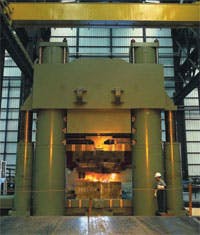
What weighs 2650 tons, stands more than 60 ft tall, and can generate 40,000 tons of force? The answer: the world’s largest all-forged-steel closed-die hydraulic press. This press is installed, commissioned, and functioning in Shultz Steel’s South Gate, Calif., facility.
The 53-year-old company, which still operates under the leadership of its founder, Gordon Shultz, manufactures parts for commercial and military aircraft, submarines, rockets, and missiles. Customers include Boeing and B.F. Goodrich, as well as the US government. This $30 million hydraulic press is a key element in Shultz Steel’s recent $62 million expansion.
The new press was built — to Shultz Steel’s design and specifications — in the city of Muroran in northern Japan. It is one of just a handful of such massive devices worldwide. In a synergistic arrangement, the high-strength forged components used to construct this press allow it to have a smaller overall envelope than other presses built from castings; yet it still can generate the large forces needed to compress metal-alloy billets into forging dies to produce parts that are exceptionally hard and resistant to failure.
Design objectives
The controls and programming for this machine had to meet some challenging objectives:
- the multi-pump press must stop its 1700 tons of moving parts within 0.25 in. of the return set point — with no more hydraulic shock than what would occur if returning with a single pump forging size (or ram-position) control must hold within ± 0.04 in.
- tonnage control must hold within ± 640 tons
- the press must transition from approach mode to pressing mode within 0.25 in. of the slowdown set point — again with minimal shock
- both size and tonnage controls should keep the pumps loaded for as long as possible — to promote rapid die filling, and
- the pump/motor start sequence and pumploading sequence should recognize if any motors are locked out or disabled, and which pumps are already running.
Hydraulic overview
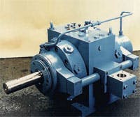
With two 66-in. diameter and two 46-in. diameter main rams, four 20-in. diameter return rams, and an 84-in. press stroke, plus an approach and return speed of 7.5 in//sec, this machine obviously calls for a lot of flow. At the heart of its hydraulic system are 24 Oilgear-Towler Model PFCS axial-piston pumps. Running at 1800 rpm, these pumps deliver 207 gpm each, at pressures up to 6250 psi. The press control combines flow from all pumps for maximum approach speed; from half of them for maximum return speed. The PFCS pumps can be configured for three separate deliveries — 13, 23, and full flow. Three of the pumps on the press are arranged for split delivery so their partial flow can be used to fine-tune some of the press motions. The other 21 pumps produce single, full delivery.
Manifolds and valves
Four valve manifolds control all the flow from the 24 main pumps. The ejector manifold (a 45.5 × 31.5 × 24 in. block) handles the three pumps configured for dual delivery. The ejector cylinder is available to push finished forgings out of the dies, if necessary. Solenoid-operated, seated-type bypass valves on the manifold direct flow to the main rams or to the ejector cylinder. This manifold also houses a relief valve for the three pumps. Pressure is set at 6250 psi when using the pumps’ flow for the main press, or at 5000 psi when sending flow to the ejector. On the press side of the main-ram admission valve, a 63-mm servo-operated relief valve controls the pressure in the main rams.
The main ram manifold (a 46 × 45 × 32 in. block, with a second, smaller manifold to control the prefill valves) handles 12 of the single-delivery PFCS pumps. Flow from this manifold is delivered to the main and return rams. This manifold also houses the valve that controls the fast gravity approach. This mode lowers the upper die without hydraulic pressure — resulting in higher speed. A 100-mm servo-operated 2-way seated-type bypass valve controls the die motion and achieves smooth acceleration and deceleration. The servovalve accurately slows down and stops the die prior to actually contacting the billet. This positions the upper die close to the forging before the press goes into the forging stroke. A 63-mm servo-operated relief valve then controls the main press tonnage.
The 9-pump admission manifold houses the admission valve that ports flow from the remaining nine full-delivery PFCS pumps into the main rams.
The decompression manifold houses a pair of 100-mm solenoid-operated seated bypass valves that smoothly decompress the system from 6250 psi in 1 to 1.5 seconds. This function is assigned a separate manifold because of the large size of the valves.
All the solenoid-operated bypass valves are Oilgear-Towler’s 2-stage design that controls the first stage of the valve with 500-psi pilot pressure. The first stage then shifts the poppet in the valve’s second stage. This design ensures repeatable performance irrespective of the actual system pressure.
Two special prefill and exhaust valves were designed for this press. One is sized at 350 mm and rated for 7000 gpm, the other sized at 450 mm and rated for 14,500 gpm. Both are connected to a pair of large air-loaded prefill tanks. They keep the system filled with fluid during gravity-powered movements, and get fluid out of the rams’ way during retraction.
Modes of operation
To prepare the press for a specific job, Shultz Steel’s forgemaster makes control settings according to experience. (The control then commits these settings to memory for the next time such a job is scheduled.) The control offers several operating modes:
- press to position with an accuracy of ± 0.04 in. under any tonnage range. (Actual accuracy is within 0.02 to 0.04 in. of set size up to full tonnage.) The control adjusts for the inevitable bed deflection, press tilt, and frame stretch
- press to tonnage with a specified accuracy of ± 640 tons. (In fact, test forgings achieved an accuracy of ± 300 tons within the set tonnage)
- press to position with tonnage override — a combination of the two previous modes, and
- clamp or approach to size without tonnage — the previously explained fast-gravity approach.
Pump-loading routine
The pumps’ prime movers are 12 double-shafted 1200-hp electric motors with one pump mounted on each end. The motors and starters were sized to withstand an intermittent overload to 1500 hp for two to three seconds without any problems. The starters and motor windings also are monitored for over-temperature to prevent long-term damage from this intentional shortterm overload. Even with these precautions, it is important to load the pumps in an energy-efficient sequence.
A pump-loading sequence was developed so that the lead split-delivery pump is always the first to load and last to unload. The pump-loading order then continues loading one pump at a time from each header group until every motor has one pump loaded. The sequence next loads the second pump on each motor in the reverse order of the first group. For example: if 24 pumps are required, the lead pump is first to load. The 13th pump to load would be on the same motor as the 12th pump, and finally, the 24th pump to load would be on the same motor as the lead pump. (The return pump-loading sequence is similar except that only 12 pumps are used.) Because the lead pump works hardest, the control rotates the leadpump assignment to equalize wear.
This loading sequence accomplishes several things. First, the admission valves in each manifold have more time to open with the flow from a single pump before additional pumps are staged in because only one pump from each header group at a time is loaded. This provides a more gradual acceleration of the oil column in each header.
Second, motor loads are reduced because the second pump on each motor is loaded last and unloaded first. If a forging job calls for only 12 pumps and all 12 motors are running, then the control will only load one pump per motor. Likewise if the press is returning with only six pumps required and all six return- pump motors are running, the control will only load one pump per motor. This reduces the peak current draw for the main electric motors.
Gordon Ford is systems engineering manager and Greg Gauper is electrical design engineer, both with The Oilgear Co., Milwaukee. Contact them by telephone at (800) 558-6636, or visit www.oilgear.com.


