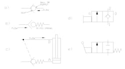
Moving on to example c), I have shown a pilot-to-open check valve. The difference between this and the first two valves is the pilot line going from the B-line on top to the seat of the check valve below. First imagining the pilot line does not exist, what would happen should we try to pressurize port B to lower the cylinder? I don’t think I have to point out the cylinder will not retract … so I will not point out the cylinder will not retract. Fluid has nowhere to go out the A port of the cylinder, so pumping in to the top has no effect.
However, since we do have a pilot line, all our problems are solved; our romantic relationships, our credit card debt and the energy required to open up the check valve, allowing the cylinder to retract. Pilot pressure pushed the ball (more likely a poppet; see sidebar for explanation) off the seat, allowing free flow from right to left past the check valve.
Now we work our way into the symbols most often associated with directional control valves. The multi-square (some would call them rectangular) representation, most common in basic hydraulic circuits will have two, three or sometimes four of these squares in a row. Each square in a symbol represents a position of operation for the valve it describes.
The symbol in example d) is called a Two Way Two Position valve. Directional control valves are often described in ways and positions. One would assume by looking at the symbol, there is only one “way” for fluid to travel in this valve. However, the number of ways in a valve actually reflects the number of work ports. Since this valve has two working ports, we say it is a two-way valve.
The number of positions is more easily understood; just count the number of squares. Each square will represent one distinct function of the valve. For example d), my two-year-old counted two squares for me. Everything now comes full circle (or square), and we now see why it’s called a Two Way Two Position Valve. It should be clear that the ways are always expressed before the positions in the description of the valve. One would tend to avoid a slip of tongue and express this valve as Two Position Two Way and risk being excluded from reindeer games on account of one’s awkwardness. I should also point out, we can simply call it a “Two Two” valve, which is written as “2/2.”
Now, let us get back to the description of the 2/2 valve in example d). This one may not make sense to someone less familiar with hydraulic symbology, what with the check valve inside of a directional valve. Actually, the valve functions as it appears; in its current neutral, un-actuated state, flow is blocked from port 1 to port 2. Conversely, oil can flow relatively restriction free from port 2 to port 1.
Although it appears this is a valve within a valve, with the check valve inside the 2/2 valve, that part of the symbol simply tells us this is a poppet valve. By their nature, they will flow one way, and block flow the other. The rectangle extending from the left side of the valve is the actuator particular to this valve. This version represents the generic symbol for a manually actuated valve. This actuator could represent a manual override, a palm button or maybe a pulled knob.
When the valve is activated manually, it switches envelopes from the 0 (zero) or neutral position to the “a” position. Some manufacturers might call it the “1” position. Regardless, what happens in this case is it opens flow in the direction of port 1 to 2 where it was previously blocked. Easy. Peasy. Lemon. Parcheesi. Sorry … that’s just a little wild and crazy use of the English language to reward all of you whom made it this far.
Finally, we arrive at example e). This valve is in many ways the same as the first 2/2 valve. It’s manually actuated, but in this case it is clear we’re using a lever and not pushing a little brass button with a screwdriver. You will notice that the neutral condition is blocked from port 1 to port 2. However, the symbol differs from the first valve. This symbol in most cases shows the difference between a poppet valve in the previous example, to a spool valve in this example.
There are functional differences between the two valve, most important to know is that all spool valves have internal leakage between ports; no exceptions. Even “zero leakage” poppet valves still have some degree of leakage, but spool valves will have noticeable levels. Be aware of spool valve leakage when applying valves; this means load could creep, accumulators could drain or pilot signals could be lost.
The last difference is the spring shown on the right. The spring symbolizes the method in which the valve returns to its neutral position. In this case, the spring keeps the valve offset to one side. Coincidentally, we call this a spring offset. This is not to be confused with spring centered for three position valves. Upon releasing the lever, the valve will snap back to its shown position. Conversely, the previous valve had to be shifted manually between both positions.
Thanks for making it to the end, and I will wrap of directional valves and symbols in next month’s e-zine.


