This final discussion on the two-pump control method will cover two different configurations of this energy-saving servo system and also present a method whereby any of the configurations could be applied to manually controlled mobile equipment.
Alternative methods
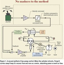
There are at least three viable configurations of the two-pump servo system. The first method was shown last month. In a second method, Figure 1, Pump B must supply makeup flow to Pump A when the cylinder extends. This means Pump A must be sized to provide cylinder cap-end flow at the design cylinder velocity. When the cylinder retracts, Pump A will have to absorb all the flow from the cap end, resulting in excessive fluid flowing toward the rod end.
This is where Pump B will function as an absorber, to carry away Pump A's excess flow. The rod-end pressure will be high (depending on the load), and Pump B will run as a motor, absorbing power as well as flow. The energy transmitted from Pump B's shaft will either be absorbed by the prime mover or sent into Pump A. This eliminates the energy losses that would otherwise occur if valves were used to control cylinder motion.
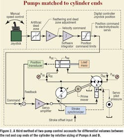
A third method just switches the pumps around so that the common pump connections are made on the cap end of the cylinder. This configuration offers an advantage: Pump A can be smaller than Pump B. This is because Pump A only has to be sized to provide rod-end flow at the maximum design speed — whether extending or retracting, whichever is greater. Pump B provides flow to the cap end during extension but absorbs the flow not needed by Pump A during retraction. For example, if the cylinder has a 2:1 area ratio, both pumps would be the same size with method two. With method three, Pump A would be twice as large as Pump B.
In either case, using pumps eliminates the significant power losses of valve control of conventional circuits — and the energy savings can be significant. This is especially true when wide speed variation is required, where valves are only partially opened over long periods of time.
Configuring the system
The preferred configuration of the electrohydraulic system provides a position-control servoloop: That's why all three configurations use a position transducer. The position loop aids setup — especially tuning of the system pressures.
As discussed last month, the ratioed stroke synchronizer mechanism keeps the pumps' displacements synchronized with one another, so the flows "add up." Each pump absorbs or issues flow as needed during a system cycle. Pressures are held in check by desynchronizing the displacements a fixed amount that causes flow from the two pumps to oppose each other. That is, the stroke offset input adjustment simultaneously causes one pump to stroke toward cylinder extension while the other strokes toward cylinder retraction. With the position loop closed, the command to stroke Pump A will cause both pump strokes to change in complimentary directions, and the cylinder will tend to stay in the commanded position.
Energizing the system
Once the system is set up, all mechanical load is removed from the cylinder. Then (assuming the servoloop and pumps are phased correctly) the stroke offset input is zeroed, and the system is powered up both hydraulically and electronically. With power on, the position servoloop will come into play, and the ratioed stroke synchronizer will cause both pump displacements to increase or decrease. This will cause the cylinder to move in a direction that will try to match the command signal with the feedback signal from the position transducer.
When the two signals are equal, both pumps will destroke, and the cylinder will stop. The system may be pressurized during this initial motion. More likely, however, some cavitation will occur. This would result from not having the stroke offset properly set.
Pressure behavior
Setting the offset input is now easy, but it does require monitoring the pressure in both the rod- and cap-end circuits. When the cylinder is stopped, the operator slowly adjusts the stroke offset input while watching the pressures at both ends of the cylinder. Knowing the design targets for rod- and cap-end pressures, the operator increases the pressures until they are at about 50% to 60% of the design targets.
Next, the stroke synchronizer is adjusted by extending and retracting the cylinder, starting at low speed, and increasing speed while still watching the cylinder pressures. If the displacement of Pump B changes too quickly, the pressures and speeds will rise. However, if displacement of Pump A changeds too quickly, pressures will be too low.
In an ideal situation, the rod and cap-end pressures will remain about the same, whether the cylinder is extending or retracting at any speed. The two pressures, however, must satisfy the area ratio of the cylinder. Therefore, with the 2:1 area scenario, the pressures should also have a 2:1 (rod end to cap end) ratio.
The subtle part of this situation is that the pumps' internal leakage resistances are used to set the pressure. It may be difficult to adjust or maintain target pressures if the pumps have very high volumetric efficiencies. In such cases, an external bleedoff path should be added. However, this bleedoff should not be great enough to significantly compromise the pumps' overall efficiencies.
Mobile hydraulics
What about applications in manually controlled, mobile equipment? The two-pump control adapts quite well to manual control — and with no reduction in the promised energy savings. Manual cylinder control normally involves deflecting a lever or joystick to control the direction and velocity of a cylinder. This is, essentially, a closed-loop position control — with the human operator closing the control loop.
Referring to Figure 1, if the operator shifts the joystick a fixed amount and holds it there, the pumps will stroke, the cylinder will extend, and it will stop when the feedback position coincides with the command. If the operator moves the joystick a little more, the cylinder will extend a little more — stopping, again, when feedback equals command.
This can be a useful system in the lift function of a fork lift, for example. The operator could set the joystick an amount that approximately sets the forks at, say, the height of a storage bay. Then, with a small thumbwheel on the joystick, he would tweak the position command to get the precise height, then proceed to remove or deposit the load.
But what about the situation where we want a conventional velocity command from the joystick? Can the control system of the two-pump circuit be configured so that the operator uses the joystick as a velocity control? Absolutely, but the modification does not change from a position loop to a velocity loop. Instead, the position loop is retained for all configurations. However, the controller is changed.
In the digital controller of Figure 2, the output of the joystick — normally a velocity control — is sent through four cascaded digital algorithms. The first is an artificial dead zone that the operator can set and tune for personal preferences. The second is an amplifier that scales the command to the proper level in a digital system. Next is a software integrator, the function of which is to convert the joystick output to a position control system.
The next step is a limit control that simply clips the maximum command to stay within the calibrated range of cylinder travel. In this system, if the operator moves the joystick some fixed amount, the integrator starts ramping up at a rate determined by the amount of joystick shift. The position servoloop then moves at that ramp rate in attempt to match the cylinder feedback signal to the command. Thus, the joystick appears to be a velocity controller to the operator.
Summarizing the concept
Pump control can definitely offer significant energy savings compared to equally sized valve controlled systems yet retain complete flexibility of control and applicability. The disadvantage is that two pumps must be dedicated to each of all functions to be operated simultaneously. However, no valves are needed at all, and the energy savings can quickly offset the initial cost of a few extra pumps — especially in high powered machines.
The book on electrohydraulic pressure control
The soft-bound book contains 154 pages and costs $59.95, plus shipping and handling. To order, or for more information, including a detailed table of contents describing all topics discussed, call IDAS Engineering Inc. at (877) 432-7364; (262) 642-7021; e-mail [email protected], or visit www.idaseng.com.


