Motion Control: Digital resolution and other digital subjects — Part 3
Editor's note: This is the third installment in a seven-part series on digital resolution and other subjects. Read the rest now: Part 1, Part 2, Part 4, Part 5, Part 6, and Part 7.
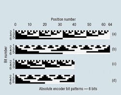
In continuing the discussion from last month, we now move on to explore absolute encoders. Figure 1 shows the window-shade arrangements for four different 6-bit absolute encoders. They are depicted as lying along a straight line, as in a linear motion encoder; however, they can also be generated in a rotational disc. The advantage of the absolute encoder is that it cannot “forget” where it is when power is turned off. The disadvantage is that they are more expensive than their incremental kin, and there is one channel for each bit, and one output wire for each bit, which accounts for their cost. The better the required resolution, the greater the number of bits. In fact, the resolution is given by:
R = 1/2N
where R is the encoder resolution and
N is the number of bits.
In Figure 1, all being 6-bit encoders, the smallest resolution is 1/64, meaning that the physical excursion can be resolved down to 1 part in 64. If it is a rotational system, the full circle could be broken into no smaller increment than 5.625° (360°/64). This is not a precise system. However, more bits in the figure would only serve to make the drawing more difficult to read.
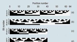
Figure 1. Shade-window schematics for four different 6-bit absolute encoders: pure binary (a), gray code (b), pure BCD (c), and gray code BCD (d).
Referring to the encoder patterns in Figure 1, observe that the white/black (logical zero/one) pattern in any given vertical line drawn through any one of the 64 increments is unique compared to any other vertical line. That is, there is a unique one/zero bit pattern at each of the 64 positions. The reading device, probably a computer or a PLC, will be able to monitor the bit pattern and “know” where the encoder shaft is in position within the resolution. The resolution becomes finer as the number of bits increases, so the position can be determined with greater precision. This is true of all the encoders represented in Figure 1.
Gray code encoders
I must point out that there is a flaw in the pure binary encoder of Figure 1(a), and it involves the transitions from one increment to the next. In a pure binary configuration, for example, five bits change in going from the 32nd to the 33rd position. It is impossible to construct the window shade edges and then position the LED-phototransistor pairs so that all five transistors switch at exactly the same instant. As a result, ambiguity always exists in making the transitions from segment to segment. The gray code was invented to circumvent this problem.
The genius of this code is that there is only one bit that changes in moving from one segment to the next. But now it is a software problem to decode the bit pattern. The bit pattern is interpreted as a pure binary number, but then this number “points” to a location in a “look-up” table, which holds the true position value for the given bit pattern. It is not a difficult programming process.
Position data are available at all times (assuming power is on) immediately. So a computer, or other interrogating device, merely has to access the several parallel wires and read the bit pattern. That bit pattern is converted to the actual position, and orders then are issued to move forward, backward, or remain in the current position. All this is done in the computer with the control software.
Magnetostrictive transducers
When the decision is made to use an encoder as a position transducer, it is usually dictated by the fact that the control system is digital. On the other hand, reports from the field suggest that most electrohydraulic motion servo systems use only analog sensing and control. A few viable analog position transducers exist, but the magnetostrictive type has been the transducer of choice for implementation in hydraulic cylinders. Here are some reasons why:
• Technologically, they are highly developed and don’t produce any major surprises, even to first-time users.
• They are available from several different suppliers.
• Either digital or analog outputs are available.
• They do not rely upon physically contacting and abrading parts in order to work.
• Designs have been developed that are buried inside the relatively safe confines of the cylinder envelope. Magnetostrictive transducers can also be mounted outside the cylinder, if that configuration is desired.
Of course, with advantages come disadvantages. Here are some limitations of magnetostrictive transducers:
• Some models exhibit a considerable temperature sensitivity.
• Internally mounted versions require the cylinder’s piston rod be machined (commonly called gun drilling) to accommodate the transducer’s waveguide tube as the cylinder’s piston extends and retracts. The piston rod’s outside diameter must be at least 1.375 in.
• Even internally mounted versions add to the final package envelope dimensions.
• They are not the most expensive transducers, but neither are they the least expensive.
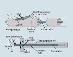
Magnetostrictive transducers use a sonar-like process to detect position. Figure 2 shows permanent magnets mounted to form a ring in a recess in the piston. The cylinder rod has been gun drilled to accommodate the waveguide tube. In operation, a current pulse applied to the center wire in the tube creates a circumferential magnetic field around the wire. This magnetic field interacts with a magnetic field of the piston-mounted permanent magnets. This interaction causes a torsional reaction in the tube — a phenomenon called magnetostriction. This physical reaction is a result of the fact that a ferromagnetic material changes its physical dimensions in the presence of a magnetic field. Furthermore, the change takes place only in the region of the piston-mounted ring magnets.
The torsional reaction is a mechanical event, and it causes a torsional displacement wave to travel back toward the current generator at the speed of sound in the waveguide tube. An instant later, the torsional wave arrives at the sending end of the tube, which has been outfitted with a small bar magnet wrapped with a coil. The tiny motion of the magnet induces a speed voltage into the coil. Measuring the time delay between the initial current pulse and the time when the “echo” torsional pulse is received enables determining the position of the piston.
LVDTs
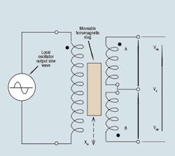
The linear variable differential transformer (LVDT), Figure 3, is an electromagnet device for measuring mechanical position or movement. It consists of a primary transformer winding and a dual secondary. Design of the transducer is such that it is fed an AC excitation frequency from 1000 Hz to about 10,000 Hz, which is normally generated using an electronic local oscillator. The amplitude of the excitation is only a few volts — in the range of 2 V to 10 VRMS.
Figure 3. The LVDT has a single primary winding and dual secondary so that the amplitude and phase vary with slug movement.
The magnetic coupling between the primary and the secondary changes with the position of a ferromagnetic moveable slug. The slug does not have to contact anything within the LVDT for it to function; it relies solely on magnetic electrical coupling.
The slug is connected to that external member whose position is to be measured. As the slug changes position, the change in coupling causes the V0A and V0B ac output voltages to change. Because of the way the secondary coils are connected, the end-to-end voltage, V0, is the instantaneous sum of the two components. Also, the coils are phased so that they are 180° out of phase with each other.
When the slug is placed in the precise electrical center, the output sum is zero, putting the LVDT output at null. The V0A voltage, which has the same phase as the primary excitation, is of the same amplitude as V0B. However, because of the 180° phase shift, their sum is zero.
When the slug moves upward, the V0A voltage increases, and the V0B diminishes to where their sum is not zero but has the same phase as V0A. On the other hand, when the slug moves downward, V0B increases while V0A diminishes, creating a summed output voltage with the 180° phase.
In summary, then, the output voltage has the same phase as V0A when the slug is above center, and the same phase as V0B when the slug is below center. And, of course, the amplitude of the output varies as the slug moves. The farther it is from center, the greater the output.
Basic Electronics for Hydraulic Motion Control
This is where your basic electronic training starts. This book, unlike many others, is written specifically by a practitioner of the hydraulic art for engineers and technicians working in hydraulics, but it teaches you all you ever needed to know about electronics. Your personal understanding of hydraulics is your ticket to learning electronics with this book, which is filled with analogies to simplify the understanding of concepts.
Everything you wondered about and need is here: transducers, interfaces, signal conditioners, pulse width modulation, controllers, amplifiers, transistors, analog electronics, digital electronics, and much, much more. It is a must read and reference for anyone interested in certification in the exploding technology of electrohydraulics.
It uses your knowledge of fluid power to help you learn and understand electronics. Order your copy now and get the book that makes electronics fun and easy to learn.
Authored by Jack L. Johnson, P.E., edited by Hydraulics & Pneumatics, and published by Penton Media, the hard cover textbook (ISBN 0-932905-07-2)contains 438 pages and sells for $59.00, plus shipping and sales tax. To order, or for more information, visit the Bookstore and download the order form.
