Pulse width modulation (PWM) has been used successfully in electronic control circuits for at least forty years. It is an efficient method for controlling a large amount of output power while expending a relatively small amount of power in the controller itself. No matter how small, the sources of inefficiency in the electronic PWM circuit stem from the finite switching time of solid-state controlling devices and the finite conducting resistance of the switching device when in its on state. The extremely short switching times of electronic devices allow the efficient use of PWM at frequencies in the kHz range, so the range of suitable applications is fairly broad.
On the other hand, using PWM to perform hydraulic switching requires valves, whose switching times must be measured in tens or even hundreds of milliseconds — not microseconds or nanoseconds as in the case of electronic circuits. The result is that improperly implemented PWM hydraulic circuits produce unwanted vibrations and pulsations at frequencies that can be transmitted to output actuators. This possibility exists in the case of the PWM regulated hydraulic pressure source.
To investigate this phenomenon, I constructed a PWM-controlled, constant-pressure power supply typical of those used in electrohydraulic servo mechanisms and motion control systems. Representative test results can be displayed and analyzed, and a practical design methodology is outlined that can be used by others wishing to apply the PWM method to regulate pressure from a power unit supplying more than a trivial amount of power to a dynamic load. This applied engineering analysis aims to determine the extent a PWM-regulated pressure source can be constructed using a fixed-displacement pump with augmenting accumulator as compared to the conventional method using a pressure-compensated pump.
Effects of non-constant pressure
Having constant pressure at the servovalve's pressure port is critical in motion control systems using the positional servomechanism that follows a motion profile. When the pressure port is maintained at a constant pressure, the accuracy of the motion control system improves. Non-constant supply pressures affect the servo system adversely in three significant ways.
First, if the supply pressure varies when the servomechanism is in a dwell, or fixed position, the variations are propagated to the servo actuator in a way that upsets the force balance. Therefore, the actuator moves, seeking a new point of force balance. This results in a new value for the error signal, and, as its name implies, results in a positioning error. In a machine tool, for example, this can result in machined parts that must be scrapped.
Second, in critical applications — say, a flying cut-off — the flow demanded by the axis undergoing acceleration causes a reduction in supply pressure. This forces the servovalve to open more fully than if the supply pressure had not dropped. The pressure reduction further causes an undesired variation in actuator speed. This will either cause an error in cut-off length or demand a time delay for both the supply pressure and the servo axis to settle, potentially reducing machine productivity.
Third, in multi-axis machines, commanding one axis to move will result in a flow demand and subsequent transient pressure reduction. Other axes that may be at dwell will "feel" the pressure variation at their own respective P-ports. The result can be twitching in the otherwise stable axes.
Dealing with less than ideal
No pressure source can be made truly constant. The pressure variations can only be reduced to where they will result in positioning and velocity errors within tolerable limits. Every application has its own set of application requirements, along with allowable speed variations and positioning errors. Clearly, then, special attention must be paid to the integrity of the pressure supply source in the most critical applications. The only thing separating critical applications from the non-critical ones is the amount of error that can be tolerated.
If we could build "ideal" pressure sources, which would not vary under any circumstances, we'd have a happy state of affairs. But such a power unit is at once impracticable and impossible. We can only strive to keep the variations within tolerable limits.
The methods for predicting the degree of servomechanism error that can be expected in the presence of a given supply pressure variation are well documented. But rather than repeating the methods, we will instead concentrate on those design features that will achieve a specific pressure variation.
The general process of maintaining a "constant" pressure in the face of flow variations (disturbances) is referred to as pressure regulation. Countless applications require constant-pressure power supplies. But the aim of this investigation is to evaluate the PWM pressure control method, and devise a design methodology for
anyone wishing to implement the concept. Therefore, it is a foregone conclusion that constant pressure is required by the application.
A break from convention
The conventional method of maintaining a constant pressure in the face of load flow variations uses a variable-displacement, pressure-compensated pump with an isolating check valve and an augmenting accumulator. The accumulator accommodates the sudden flow demands of the load flow, and, as explained last month, is critical to the dynamic regulation of supply pressure.
Standardized methods exist for testing pressure-compensated pumps, both dynamically and in steady-state. The pressure-compensated pump is not the subject of this investigation. Rather, it is evaluated here only to provide a comparison to a pressure control method assumed to be familiar to the reader. It is the standard by which at least some judgement will be made regarding the effectiveness of the PWM pressure regulation method.
Establishing the ground rules
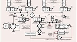
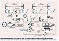
The power unit used as the subject of this report is drawn in hydraulic schematic form below. It consists of an engine driven, variable-displacement pump with appropriate valving and accumulators to maintain relatively constant pressure under varying flow demands.
The load consists of a time varying, but programmable, load flow. The power unit can function using either conventional pressure compensation or with PWM (on-off) pressure regulation while keeping pump displacement fixed. Next month, we'll begin analyzing operation of this power unit in some detail.


