Hydraulicspneumatics Com Sites Hydraulicspneumatics com Files Uploads Custom Inline Archive Www hydraulicspneumatics com Content Site200 Articles 10 01 2007 73302whattolook 00000047537

What to look for when studying electronics

Oct. 18, 2007
This series of articles on electronics is going to draw heavily on your knowledge of hydraulics and analogies to help demystify the electronic art. Equally important is to point out where the analogies fail to apply. In previous issues, ...

This series of articles on electronics is going to draw heavily on your knowledge of hydraulics and analogies to help demystify the electronic art. Equally important is to point out where the analogies fail to apply. In previous issues, we’ve covered the analogous relationships between pressure and voltage, current and flow, and reservoir and electrical circuit common, often erroneously referred to as ground. Now, we’ll concentrate on what to look for as you get into this exciting and versatile technology called electronics.

With tongue in cheek, I like to talk about “chasing electrons” versus “chasing molecules of fluid.” These ideas are clearly analogous. However, the former, chasing electrons, will not serve you well in studying applied electronics.

Hydraulics is a power transmission medium, while electronics is a control medium. Also, it will be assumed that you will be more interested in applying electronics to control hydraulic machines than in designing electronic circuits. Power transmission and circuit design both lend themselves to chasing molecules, and such viewpoints are worthwhile and encouraged. If you were to design electronics, chasing electrons would be a useful endeavor. However, when you apply electronic devices that someone else has designed, you will be better served by “chasing signals.” It will be helpful to adopt a black box approach and concern yourself with what happens to a signal as it passes through a particular electronic circuit.

Sometimes chasing electrons can be an aid. Ffor example, in understanding the function of the output stage of a pulse width modulation driver for a proportional valve. Also, the function of a dc power supply is facilitated by pursuing the electrons as they dash around the circuit.

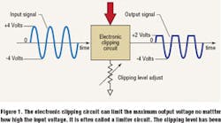
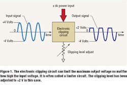
The black box approach can be facilitated with an example. In Figure 1, there is a specialized electronic circuit called a clipper, or clipping circuit. The function of a clipper is to limit the output to some predetermined or adjustable level no matter what the input level is. In the example, the input signal is a sine wave with a peak amplitude of 4 V and a minimum amplitude of 4 V. It is a continuous wave, even though only three complete input cycles are shown in the figure.

There is a number of things to be emphasized. First, the sine wave goes into the circuit at full plus and minus amplitudes, but the peak of the output voltage is limited to +2 V, which is exactly what the clipper was designed to do.

Second, the circuit is equipped with a clipping level adjust control, a potentiometer, or pot, so that the peak level of the output can be set by the user in the application. We don’t know the range of the adjustment, but it is reasonable to expect that the limit could be set anywhere between 0 V and +4 V, or even more. Also, we don’t know if the limit adjustment is itself limited to only positive levels, or, if it can adjust for some negative values, too. To determine such matters, we would need documentation from the circuit designer in the form of a users’ manual.

Third, as with almost all electronic circuits, the clipper requires an external dc power supply labeled as ±dc power input in the figure. This might be simply a battery, such as the one in your calculator, or it may be an electronic power supply like the one in your desktop computer. Such power supplies derive their energy from the ac power line, and therefore require a power cord connection to a wall outlet or other ac power connection method.

Fourth, the common point for the clipping circuit is drawn as a small downward pointing arrow just at the bottom of the clipping level adjust pot.

It must be emphasized that this is not mother Earth, merely the common point for the clipper and its power supply. Indeed, there may not be any connection to mother Earth at all. Your calculator has no mother Earth connection, but it does have an internal common, and, sadly, its designers probably refer to the point as “ground.” Be forewarned, electronic designers throw around the term ground, and the user has to be aware that real connections to mother Earth have serious implications when it comes to electronic noise. It may help the noise, or it may make it worse. We’ll talk more about that later.

Fifth, it is very helpful if you can accept what the circuit does without really understanding how it does it. It’s certainly okay to know how it works, but it is not absolutely necessary.
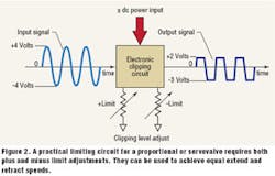
Sixth, this circuit has practical value in electrohydraulics. It can be used to limit the amount of current and voltage that are sent to a proportional or servovalve. For example, single rod-end cylinders extend and retract at different speeds. By setting the clipping level, the user can limit the amount by which the valve spool is shifted, and by “tuning” the circuit, extend and retract speeds can be made the same. But, there is a little more explanation needed. That is, the clipping circuit will have to be designed so that both negative and positive values can be limited, so there is limit control for both directions of valve shift. The designer of such a circuit will most likely not call it a clipper — rather, it will be called a limiter, or some other user-friendly name. A practical valve stroke limiter is shown in Figure 2. Take note of the differences. There are now two level adjustments, one for each direction of spool shift. One has been adjusted to +2 V and the other to 3 V. In the proportional valve control circuit, the input would likely NOT be a sine wave, but rather just some arbitrary input or command voltage. But whatever the input, the maximum plus and minus values would be determined by the settings on the clipping level adjustments, also called the ± limit controls in Figure 2. In this example, the limits have been adjusted to +2 and 3 V respectively.

Seventh, note that in both figures, there is a ± sign in front of the dc power supply notation. This means that the circuit requires a power supply that provides both plus and minus voltages with respect to circuit common. Such power supplies are called bipolar power supplies. Not all electronic circuits require bipolar power supplies; however, in the analog portions of most electrohydraulic systems, they are almost universally required. At the very least, the electrohydraulic applications engineers or technicians are advised to know what type is required, because they often are required to select a power supply for their applications.

Eighth, please note that indeed, there are electrons running around inside our clipper, and we could chase them if we wanted to. However, we don’t need to know a whole lot more about them, if we can accept the function of the circuit.

In the next issue we’ll look at one of the most universal electronic circuits: the amplifier. It is also the most important device in electrohydraulic systems.

Continue Reading

Handbook Simplifies Advanced Aspects of Mobile Hydraulic Controls

May 10, 2017
Author Brendan Casey lays out his hydraulics know-how that he acquired over 27 years in a simple handbook made for people that want to improve their skills in troubleshooting ...

Terrain Leveler is All Hydraulic

Feb. 22, 2017
Hydraulics helps surface excavation machine extract ore reserves that might otherwise get left behind.

Sponsored Recommendations

MONITORING RELAYS — TYPES AND APPLICATIONS

May 15, 2024
Production equipment is expensive and needs to be protected against input abnormalities such as voltage, current, frequency, and phase to stay online and in operation for the ...

Circuit Protection Devices & Busbars

March 13, 2024
With experienced Product Engineers and Customer Service personnel, Altech provides solutions to your most pressing application challenges. All with one thought in mind - to ensure...

All-In-One DC-UPS Power Solutions

March 13, 2024
Introducing the All-In-One DC-UPS, a versatile solution combining multiple functionalities in a single device. Serving as a power supply, battery charger, battery care module,...

Motor Disconnect Switches

March 13, 2024
With experienced Product Engineers and Customer Service personnel, Altech provides solutions to your most pressing application challenges. All with one thought in mind - to ensure...