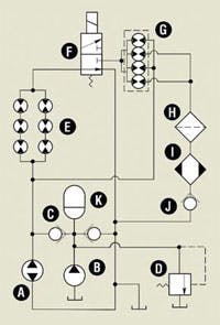
Schematic circuit diagram of closed-loop hydrostatic drive with regeneration circuit (shown in its nonregeneration mode). Case drain lines are omitted to simplify the drawing, and although HSTs typically use a single reservoir, multiple reservoirs are drawn for the same reason.
Flow from half of the sections of the rotary flow dividers is routed to a tee connection upstream from the motors in the high-pressure side of the hydrostatic loop. Thus, the branch circuit provides regenerative flow into the hydrostatic motors — for increased speed. Flow from the balance of the sections of the rotary flow divider passes through the filter, cooler, and check valve J to a tee connection on the low-pressure side of main pump A.
The role of flow dividers
Rotary flow dividers exhibit an intensification characteristic. If resistance to flow out of one section of a rotary flow divider exists, outlet pressure from that section can be intensified to a level higher than the supply pressure. The intensification force is applied by the other sections of the flow divider — if flow from those other sections is encountering a much lower resistance.
Such is the case with this circuit. Pressure builds up on the outlet side of the flow divider until it becomes high enough to join in with main pump flow going into the hydraulic motors. The circuit stabilizes when approximately half of the pressure generated by pump A drops across at least one hydraulic motor, while the other half of the generated pressure drops across the sections of the flow divider. The end result is that if pump A is putting out 20 gpm, after valve F is shifted, 40 gpm will go into at least one motor. And if the pressure drop across at least one hydraulic motor is 2000 psi, the resistance to flow at pump A is approximately 4000 psi.
These numbers are theoretical. In practice, and in accordance with the Second Law of Thermodynamics, the house takes its cut. Losses are due to internal leakage and pressure drops through various elements of any hydrostatic drive, with or without regeneration. Energy is not created or destroyed by the flow dividers, merely changed in form.
Rotary flow divider G in the schematic diagram is a 4-section unit, such as the Model FD 18181818 Roller Stator gerotor type from White Drive Products, Hopkinsville, Ky. This component was selected because of its modest internal leakage and relatively low pressure drop — typically 140 psi at 40 gpm fluid flow. Pressure drop steals horsepower and adds heat. For vehicle drives, both the extra horsepower requirement and the need to dispose of extra heat are undesirable. (Although high-capacity, gear-type rotary flow dividers with low pressure drop exist, they tend to be more expensive and less efficient across the lower speed ranges than gerotor flow dividers.)
Additional functionality
Variations in the amount of regenerated flow can be achievable by varying the ratios of sections of the rotary flow dividers. Smaller gerotor sections in the regeneration line would make more pressure drop available for work across at least one hydraulic motor. Conversely, larger gerotor sections result in less pressure drop being available, but more flow.
When pump A is reversed, what was the low-pressure side of the closed loop becomes the high-pressure side. In this mode, de-energized valve F and check valve J protect the cooler, the filter, and the flow divider from reverse fluid flow at high pressure.
In vehicle drive systems, the hydrostatic pump would typically be a bidirectional, variable-displacement, axial-piston model. In industrial drive systems, the pump is not necessarily an axial-piston type, nor does it have to be bidirectional; it could have fixed displacement. (If the pump is not bidirectional, check valve J is not required.)
There is another benefit to the circuit that does not involve regeneration. For conventional hydrostatic drives with bidirectional pumps, the approaches to proper filtration and cooling are limited. High-pressure filtration arrangements are expensive, so typically they are not used on mobile equipment. Similarly, coolers that can withstand the high pressures of the hydrostatic loop also would be heavy as well as expensive. Consequently, most filtration and cooling designs are limited to case-drain or charge-pump flow, or hot-oil shuttle arrangements where only a small percentage of flow is cooled and filtered at a time. The bulk of the flow often is not properly filtered or cooled, opening the door to accelerated component wear.
The filter and oil cooler in the regeneration circuit only have to deal with relatively low-pressure flow. Whenever valve F is energized, half of the flow in the circuit goes through the filter and cooler at low pressure.
George Morgan, P. E. is a registered patent agent in Evansville, Ind. For more information, contact him at (812) 476-4065 or e-mail [email protected]. For more information from White Drive Products, call (270)-885-1110 or visit www.whitedriveproducts.com.


