BOOK 2, CHAPTER 5: Counterbalance Valve Circuits
Counterbalance valves
Some actuators with running-away (or overrunning) loads will let the load free fall when the directional valve that controls the actuator shifts to lower the load. Cylinders with large platens and tooling or hydraulic motors on winch drives are two examples of such actuators. When the directional valve shifts, an overrunning load forces the actuator to move faster than pump flow can fill it. Oil at high velocity leaves one end while the opposite side starves for fluid. A vacuum void forms in the inlet side of the actuator that must be filled before applying force. Any running-away or overrunning load needs some method to retard its movement.
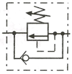
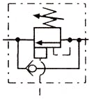
Figure 5-3 shows the symbol for an internally/externally piloted counterbalance valve. This valve has the best of both systems. As the load extends, internal pilot supply gives smooth control with little energy loss. After work contact, as system pressure builds, the external pilot fully opens the counterbalance to relieve all backpressure in the cylinder.
. Spool designs leak at a rate of 3 to 5 in.3/min, thus allowing actuator creep. Poppet designs leak at only 3 to 5 drops/min, minimizing cylinder creep. (Because hydraulic motors bypass internally, a counterbalance only works with a moving load. The designer should apply a braking method to hold a hydraulic motor at rest.)
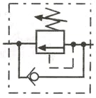
Internally piloted counterbalance valve
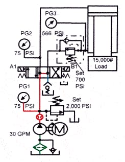
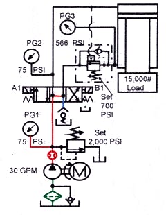
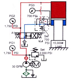
Figure 5-4 pictures a circuit with a running-away load. This circuit demonstrates the operation of an internally piloted counterbalance valve. The cylinder in Figure 5-4 has a static pressure of 566 psi in the rod end due to the 15,000-lb load on the 26.51- in.2 area. (15,000 / 26.51 = 566 psi). An open-center directional valve unloads the pump and keeps backpressure off the counterbalance valve outlet and pilot port. The cylinder holds in any position if the counterbalance valve is set correctly and does not leak. Set the counterbalance approximately 100 to 150 psi higher than the load-induced pressure.
Normal procedure for setting a counterbalance valve is to turn the adjusting screw to its highest pressure before raising the cylinder. After starting the pump, energize the directional valve and carefully raise the load a short distance. With the load suspended, deenergize the directional valve. A working counterbalance will hold the load suspended and gauge PG3 will show the load-induced pressure. Now start lowering the counterbalance pressure setting slowly. When the cylinder begins to creep downward, increase the pressure until creeping stops. Then continue turning the adjusting control in the same direction another to turn. After setting the counterbalance this way, power the cylinder down and notice the pressure reading on gauge PG3. Pressure should be approximately 700 to 750 psi. Any time the cylinder loading changes, repeat the above process. Resetting the counterbalance valve keeps the cylinder from running away and reduces energy loss with a lighter load.
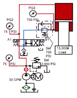
When the directional valve shifts to extend the cylinder in Figure 5-5, oil from the pump flows into the cap end of the cylinder and pressure starts to build. When pressure in the cap end of the cylinder reaches about 75 psi, the cylinder should start to stroke. (This is because it builds an extra 140 psi in the rod end, adding to the load’s 566 psi.) At this point the cylinder starts to extend and continues to move as long as the pump supplies oil at 75 psi or higher to the cylinder cap end. If pump flow changes, cylinder speed changes also.
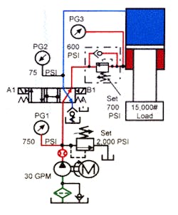
While the cylinder is retracting, Figure 5-6, pump flow bypasses the counterbalance valve through the integral bypass check. The counterbalance valve offsets the potential energy of the weight on the rod end of a cylinder. The 15,000-lb force in this figure cannot do useful work when using an internally piloted counterbalance valve. (See Figures 5-13 through 5-15 for energy loss and heat generation for different types of counterbalance circuits.)
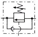
Externally piloted counterbalance valve
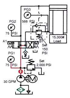
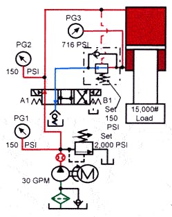
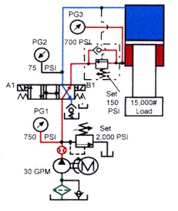
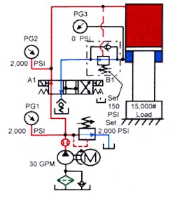
Figure 5-7 shows an externally piloted counterbalance valve circuit. (This is the same cylinder arrangement shown previously.) Notice the counterbalance setting of 150 psi with this circuit. Because this is an externally piloted counterbalance, it operates at a much lower setting. If the load changes, the counterbalance setting does not change. Load-induced pressure does not affect set pressure. Theoretically, set pressure could be 1 psi and the load would not move. The cylinder would only extend when the counterbalance valve’s external pilot port sensed 1 psi at the cylinder cap end.
On most externally piloted counterbalance valves, the minimum pressure setting is 100 to 200 psi. This keeps the counterbalance valve from hunting. Hunting starts when the valve sees enough pressure to open, but then opens too wide. The cylinder runs away when the valve opens too much and pilot pressure drops. When pilot pressure drops, the counterbalance valve closes and the cylinder stops. After the cylinder stops, pilot pressure builds again. The process repeats and continues to the end of stroke. The higher the load-induced pressure, the greater the hunting problem. (On some systems it is possible to add an orifice in the pilot line to slow the pilot supply response and reduce hunting. This orifice fix is difficult to get right and may cause other circuit problems.)
Energizing the directional valve to extend the cylinder in Figure 5-8 sends pilot pressure to the counterbalance valve from the cap end cylinder line. Once pressure in the cap end cylinder line reaches 150 psi, the counterbalance opens and the cylinder extends. As long as there is enough pilot pressure to keep the counterbalance open, the cylinder moves forward. Increasing, decreasing, or stopping pump flow causes the cylinder to respond accordingly, but never to run away.
When the cylinder meets the load, pressure in the pilot port of the counterbalance continues to increase. When pilot pressure goes above the counterbalance setting, the valve opens fully and drops all backpressure on the cylinder rod end. With no backpressure on the rod end, the weight energy generates extra downward force. The externally piloted system saves energy by eliminating all backpressure when performing work. Figure 5-9 shows the flow paths after the directional control valve shifts to retract the cylinder.
Some manufacturers make counterbalance valves with internal and external pilots. These internally/externally piloted valves provide the best of both systems. They use the internal pilot to lower the load smoothly and the external pilot to drop all backpressure when performing work, thus avoiding loss of down force. In addition, internally/externally piloted counterbalance valves don’t hunt.
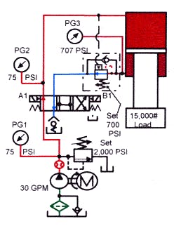
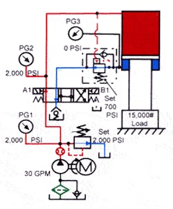
Figure 5-10 shows a schematic drawing with an internally/externally piloted counterbalance valve. In the at rest condition, the external pilot drains to tank through the directional valve. The internal pilot has static pressure from the load-induced pressure on the rod end area. Setting the counterbalance pressure approximately 25% higher than static pressure (1.25 × 566 = 707 psi) means that when pressure at the cylinder cap end rises to approximately 75 psi, the cylinder starts to stroke.
To see how cylinder thrust changes with different counterbalance valve pilot options, look at Figures 5-13, 5-14, and 5-15. These circuits show each type of counterbalance piloting system in the working condition — with pressures, forces, and effective force listed.
Machine thrusts with different counterbalance valve pilot options
An internally piloted counterbalance valve controls cylinder extension smoothly, but reduces thrust during the working portion of the cycle.
The counterbalance valve more than cancels the weight of platen and tooling that gives an energy loss of approximately 16%. Approximately 7.5 tons of force from the rod end weight must be raised during every cycle but does not do any work as the cylinder extends.
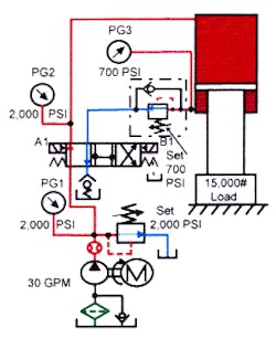
Externally piloting the counterbalance valve, Figure 5-14, requires about twice as much pressure to extend the cylinder. However, upon reaching the work, the loss of backpressure on the cylinder increases the cylinder force and more than makes up for the loss.
The schematic shown in Figure 5-14 has the same downward force as Figure 5-13 — a total of 115,540 lb. The difference is that there is no upward force in Figure 5-14. The resultant downward force of 115,540 lb is an increase of 16% over the circuit with an internally piloted counterbalance valve. This saves most of the energy expended to raise the load on the return cycle.
If at all possible, a counterbalance valve should be externally piloted. As explained previously, in some instances a cylinder might chatter as it extends if its circuit uses an externally piloted counterbalance valve. This chatter usually applies to circuits with high load-induced pressure or when the counterbalance valve is mounted at a distance from the cylinder port. The best practice is to mount the counterbalance valve directly on or very close to the cylinder port. Note that if a conductor between the cylinder port and valve breaks, the cylinder will free fall. That is why it is always good practice to use an external safety device to protect the operator and machine.
Hydraulic motor brake valve
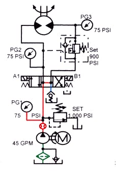
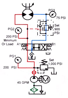
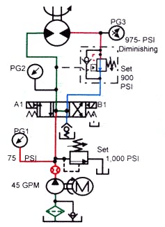
Excessive backpressure can damage a fast-turning hydraulic motor during an emergency stop situation. An open-center valve will eliminate backpressure, but the motor will continue to turn until it coasts to a stop. For a fast, non-shock stop, use a special counterbalance valve, called a brake valve. Figures 5-16, 5-17, and 5-18 illustrate a hydraulic motor circuit that uses a brake valve.
The brake valve is an internally/externally piloted valve with different pilot areas. Some designs take one eighth of the pilot pressure at the external pilot port as that set at the internal pilot port. This means, for example, that setting the internal pilot at 900 psi requires only 113 psi at the external pilot to open the valve. The actuator could be a hydraulic motor or a fast moving horizontally mounted cylinder with an over running load. In either case, a brake valve eliminates damage from stopping the actuator abruptly.
With the hydraulic motor moving, Figure 5-17, external pilot supply opens the brake valve at low pressure. As long as pressure required to move the motor is greater than the external pilot pressure needed, there is little or no energy loss. A brake valve appears virtually nonexistent as the motor runs under load. If the hydraulic motor tries to run away, say on a loaded winch, a brake valve holds against the load until the motors down port sees at least 113 psi. The load will lower only as fast as fluid enters the motor down port. A brake valve counterbalances when necessary and allows almost free flow under load.
When the directional valve shifts back to its center position, Figure 5-18, external pilot pressure drops and the brake valve begins to close. The hydraulic motor now acts like a pump, trying to force oil through the brake valve. As the brake valve starts closing, internal pilot pressure builds to 900 psi, forcing fluid through the brake valve at a 900-psi pressure drop. This 900-psi backpressure decelerates the actuator smoothly and rapidly. Setting the valve pilot pressure higher makes the stop faster and more abrupt. A lower pilot pressure setting makes the stopping time longer but smoother. In any case, stopping action is smoother and quicker than it would be without the brake valve.
The difference between this circuit and a setup using a cross-port relief valve is that setting the brake valve at a pressure lower than system pressure does not affect normal actuator operation. Also, it eliminates the danger of cavitating an externally drained hydraulic motor. Note how the path around the brake valve with a bypass check valve allows reverse free flow for opposite rotation. To stop the motor quickly in the opposite direction of rotation, install another brake valve in the opposite motor line.
