Save energy with active damping
Turn on a current music video, and any hydraulics you may see at work are probably those used on a tricked out ’81 Buick Regal, bouncing up and down to the music. But in the hydraulic systems we all know and love, bouncing is a bad thing; damping a system is much preferred.
Damping refers to the energy dissipation properties of a material or system under cyclic stress. Often, damping is used to keep unwanted oscillations out of a motion system. These systems oscillate because the energy within them cycles back and forth between kinetic and potential energy. In the case of a fluid power system, the kinetic energy is a function of mass and velocity, and the potential energy is a function of the pressure and volume of the fluid (oil or air).
Some systems are more prone to oscillation than others. Systems with a low friction-to-mass ratio and those that are “springy” and can absorb the input energy as potential energy are prone to oscillations.
Two types of damping
There are two types of damping: passive damping and active damping. Passive damping uses friction to reduce or stop oscillations in a system. Passive damping is not efficient, because the friction causes energy loss. Active damping involves reducing the amplitude and or duration of an oscillation using active means or a controller. Energy can be saved via active damping, by using a motion controller to carefully subtract or add energy at a precise time. An example of a middle ground between active damping and continuous passive damping is to use a braking system that can be selectively enabled to stop oscillations when it is desirable, or disabled (i.e., the brakes can be released) when efficient motion is required. Selective braking is much more efficient than applying friction throughout the motion cycle, but the amount of damping (friction) applied by a brake is difficult to control, and damping is often needed during the entire move — which means the brake would need to be applied to some degree all the time. Any time that braking is used, energy is wasted.
Because active damping involves a programmable motion controller, different methods or algorithms that damp the motion can be created, including damping based on selected derivatives of the motion. For instance, one may want to move a system smoothly at a constant speed. In this case the controller expects the first derivative of position (velocity) to be non-zero but it needs to monitor the second derivative of the motion (acceleration) to guard against non-zero conditions that can cause oscillations. Any oscillations in the acceleration must be damped to zero for smooth motion at a constant velocity.
The challenge of detecting errors
The ability to detect errors in the second and third derivatives is challenging, and not every motion controller can do it. Controllers that have this extra ability can exert better control when accelerating or decelerating rapidly, which is often necessary to shorten cycle times and increase machine productivity.
Closed loop systems with PID gains provide the D (derivative) gain to correct for errors between the target and actual velocity. However, this gain is not often used if the system has poor sampling techniques and coarse resolution of position feedback. Even with the highest position resolution and the most deterministic sampling, it is still a challenge to accurately calculate the second derivative (acceleration).
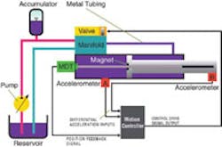
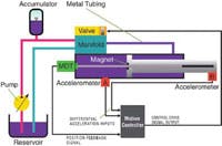
In most cases, taking the second derivative of a position feedback doesn’t work (due to sample time jitter and poor feedback resolution), but the acceleration value can be readily obtained using accelerometers, Figure 1, and the jerk or third derivative can be obtained by differentiating the acceleration (i.e., computing the time rate of change of the acceleration).
When accelerating, the desired acceleration and velocity will be non-zero, but the jerk (the third derivative of position) needs to be damped out to zero. These derivatives usually will provide all the feedback required so the motion controller can deliver good control using active damping methods.
A downside of using accelerometers is that this requires extra inputs to the motion controller and tuning of an extra gain or two in the motion controller. Also, one of the accelerometers must be physically mounted at the load, which means it is moving, with an increased chance of being damaged by the motion. Depending on the environment, the wires and accelerometer may have a very short functional life, and may not be practical.
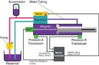
Another method of getting the approximate value of the acceleration and jerk on a fluid power system is to use pressure transducers on each end of the cylinder, Figure 2. The pressure on each side of the piston must be multiplied by the area of the piston on that side to determine the forces in each direction, and then the force in the negative direction is subtracted from the positive direction to get the net force being applied to the piston.
If one assumes the load mass is constant and there are no other forces then the acceleration can be determined (F = M A). However, that is a very big “if.” The differential force across the piston may not be the true net force. Some of the force is lost due to friction in the seals. There may be other sources of friction that will cause the net force to be different from the differential force that is calculated. Finally, if the cylinder is dead-headed against a stop, it will not accelerate at all, even though force is being applied.
We can therefore conclude that the differential pressure transducer method is not the best method for calculating the acceleration or jerk, but it can be successfully used to dampen oscillations as long as the calculated acceleration is not too inaccurate.
In this case, the gains are multiplied by the differences between the differential force and zero. The idea is that if the differential force can be reduced to zero, then the other frictional losses don’t matter and mass doesn’t matter either. If there is no force, then there will be no motion or oscillation once the set point is reached. This method works well for those systems that chatter when moving slowly due to high static friction and cylinders and masses with low natural frequency.
A third way of calculating acceleration is to use an advanced algorithm that can estimate the acceleration using the position feedback and the control output. Only newer, more powerful motion controllers will have this option. The benefit of this method is that it does not require extra analog inputs, saving labor and material costs. It does require a motion controller that can perform extra math and has extra processing power to execute the algorithms. This method also requires a dependable method to obtain a mathematical model of the cylinder that is being controlled.
These controllers should have software that makes obtaining a model relatively easy, provided the cylinder response is relatively linear (i.e., with a linear relationship between the control signal being provided to the cylinder and the resulting motion of the cylinder).
If the cylinder response is not sufficiently linear, the modeling option just described will not work, and one must use one of the first two methods of active damping. If none of the active damping choices are an option, then one must rely on passive damping or make the system stiffer. With a fluid power system this involves using a larger cylinder, valve, and pump. The extra cost of these components may make one reconsider active damping. Tradeoffs then exist between cylinder sizing, valve sizing, and the use of an active-damping-capable motion controller. The less expensive long term route is usually to buy the linear valve and use a controller capable of active damping, rather than making the cylinder diameter bigger, because the bigger diameter cylinder requires more hydraulic fluid and a bigger valve.
An active damping example
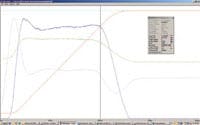
Because of the compressability of air, damping is important for closedloop pneumatic control. Figure 3 contains a motion plot showing active damping of a pneumatic system using pressure transducers to measure the differential force on the piston. The vertical axis shows the magnitude of various system parameters and the horizontal axis represents time.
In this example, the goal is to move the cylinder from 1 to 11 in. at 10 in./ sec. The actual position (red line) is shown as a function of time, increasing from the 1-in. position in the lower left toward the target position (cyan line) at the top of the screen. The control output (green line) initially makes a small increase but then hesitates because the differential force (gray line) is increasing very fast.
A motion controller without the differential force feedback would just keep increasing the control output until it was too high. Initially, the differential force is increasing due to air being added that has nowhere to go because the cylinder isn’t moving. When the differential force is greater than the frictional forces the cylinder starts to move and the differential force drops. This in turn allows control output to be increased. The speed (blue line) builds to a relatively constant 10 in./sec.
Finally, the actual position gets close to the target position, so the control output starts to decrease. As the control output decreases, the differential force decreases, because the speed of the cylinder is increasing the volume of the cylinder on the push end faster than air is being added. Eventually the differential force drops below the amount needed to overcome friction and the cylinder slows down and stops. The key point is that this controller used the differential force feedback to keep from adding too much energy (pressurized air) and thus eliminated any overshoot or oscillation.
Summary
Active damping is a much more energy efficient and more flexible option than friction damping or special cases of passive damping such as braking. In systems that are prone to oscillations, smooth and accurate motion requires the ability to control using position and its derivatives. While some controllers only have the ability to detect errors in the first derivative, others can detect errors in second and third derivatives, too. This extra capability provides for better control when accelerating or decelerating rapidly which is often necessary to shorten production cycle times. And this capability is available today for both hydraulic and pneumatic applications, using a high-performance electronic motion controller.
For more information, email the author at [email protected].


