Moving part air logic controls
Electrical and electronic devices normally control fluid power circuits. Relay logic circuits, programmable controllers, or computers are common control methods. Another way to control fluid power systems is with moving part air logic. Air logic controls perform any function normally handled by relays, pressure or vacuum switches, time delays, counters, and limit switches. The circuitry is similar, but compressed air is the control medium instead of electrical current.
Environments with high concentrations of dust or moisture are excellent places for air logic controls. There is no danger from explosion or electrical shock even in such environments. Water can splash on the controls with no effect on their operation. If there is danger of explosion, air controls cannot ignite the materials involved. Another place to use air logic is on machines that have cylinders or fluid motors but no electrical devices. Machines powered by air and controlled electrically must be supplied with both utilities -- and require two crafts to work on them. With air logic, a single craft works on the circuit and the machine parts.
A disadvantage of using air logic control is a general lack of understanding about how the components work and how to read the schematic drawings. If an air-controlled machine fails, very few people have the skill to work on it. Also, air logic with long control lines will have a noticeably slower cycle. Control lines longer than ten feet fill and exhaust slowly when compared to electrical signals. Another thing: control air quality must be above average for long trouble-free life.
What are air logic controls?
Air logic controls are basically miniaturized 3-way and 4-way air valves. The actions of the valves produce on or off functions -- like relays or switches do -- plus exhausting of the spent signal. The symbols used for air logic are similar to electronic symbols. Some manufacturers use modified electrical symbols and ladder diagrams to show circuitry.
Following are explanations of the basic air logic components with figures showing the ANSI logic symbol, an equivalent ISO graphic symbol, and a generic cross-sectional view of the element.
AND element
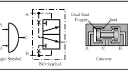
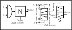
Figures 19-1 and -2 show two types of AND elements. An AND element must receive two inputs before there is an output. This assures that two functions have been completed before there is a command to continue the cycle. Another way of saying this is that there must be a signal at A and B before getting an output at C. For more than two inputs, connect AND elements in series. The first AND receives two signals and its output connects to one input of a second AND. The other input of the second AND receives the third signal making three inputs necessary before passing an output. The first AND takes two inputs but any additional input requires another AND. (See Figure 19-14 for an example.)
From the cross-sectional view it is seen that air entering the A or B port will push the dual-seat poppet onto a seat and block flow. However, when a signal is present at both the A and B ports, the lowest pressure signal will pass to the C port. This element may allow a small amount of air to pass when it receives the first signal if the dual-seat poppet is off the seat on the side from which the signal is coming. In most cases this is not enough of a signal to start the next function. If this is ever a problem, use the YES element discussed next.
YES element
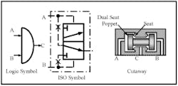
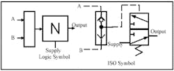
Some manufacturers supply both types of elements -- calling the element in Figure 19-1 an AND, and designating the element in Figure 19-2 as a YES. The difference between the elements is that the AND in Figure 19-1 is passive because its output is always the lower of the two inputs. In contrast, B is always the output of the YES element's two inputs. Using this feature can amplify a weak signal because it pilots the valve open at the A port while the through signal at B comes from a full pressure supply. A YES element is called active because there is a choice of which signal passes to the output.
From the drawing in Figure 19-2 it is easy to see that a signal at the A or B port cannot pass. A signal at A only shifts the dual-seat poppet; a signal at B is blocked in the at-rest condition. Any air that was present at C exhausts through the exhaust port. The flexible diaphragm above the poppet keeps air that is entering A from exhausting or producing an output. This logic element can be used to amplify a signal because of the approximately 10:1 area ratio difference between the A and B ports. This means a 10-psi signal at A can shift against a 100-psi input at B.
OR element
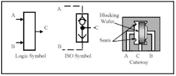
OR element symbols and a cross-sectional view are shown in Figure 19-3. (A shuttle valve serves the same purpose as an OR element.) Either input to an OR element produces an output. Pilot signals from two different sources can pass through to start the next function. Another way of saying this is that a signal at A or B produces an output at C. An OR element differs from an in-line tee because an OR passes either input to the output but does not allow the inputs to pass to each other.
From the cross-sectional view, it is easy to see how a signal entering the A or B ports can only pass out the C port. A slight puff of air may escape as the blocking wafer moves from seat to seat after an input signal, but this is usually not strong enough to start another function. Although an OR is a passive element, that is not a problem because it always passes the higher of the two signals it receives.
Stack OR elements to allow for more than two inputs. Use an extra OR for each new input after the first two signals -- with one input from the preceding OR and the other from the new signal.
NOT element
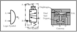
The NOT element symbols and cross-sectional view in Figure 19-4 designate an active, normally open logic element. A NOT logic element is a normally open 3-way valve. An input signal or pressure to the supply port passes through the valve until there is a pilot signal at port A. Pressurizing port A blocks supply and exhausts the output signal to atmosphere. Without a pilot signal, a NOT always returns to the normally open condition.
From the cross-sectional view you can see that supply is free to flow to output in the normal condition. A signal at the A port pushes the dual-seat poppet down to block supply and exhaust the output air. This element will block a signal as well as a supply when necessary. A diaphragm above the poppet prevents air entering port A from exhausting or passing to output. The area on top of the dual-seat poppet is approximately 10:1 in size over the shutoff seat at the supply port.
For some applications, a NOT element can replace a limit switch to indicate that a cylinder is at the end of stroke. Pressure from a cylinder port goes to port A of the NOT, holding it closed. As the cylinder strokes to the work, pressure stays the same when using meter-out flow controls. When the cylinder contacts the work, the signal on port A drops, the NOT then opens and sends a signal to start the next operation. (For a full explanation of this circuit see the author's book "Fluid Power Circuits Explained." Also see Figure 19-12 for a NOT as an end-of-stroke indicator.) Using a NOT element as a stroke-position indicator is not positive because an output signal is generated any place the cylinder stops for any reason. This always happens, whether the cylinder stopped where it should or stalled for some other reason. Because this is the case, take care using a NOT to replace a limit valve. Conversely, this feature can be advantageous when clamping different sized parts. Use a NOT element for applications where different work locations stop the cylinder and there is no safety hazard or possible part damage when the cylinder does not complete its full stroke.
Most manufacturers supply a different pilot ratio for a NOT element to be used as a limit switch. The valve function is the same but the pressure at which it shifts is lower. Some manufacturers make a special NOT element that mounts directly to a cylinder port. A port-mounted, meter-out flow control used in conjunction with this special NOT makes a compact installation.
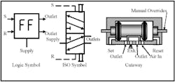
The cross-sectional view and symbols in Figure 19-5 are for a flip-flop element. A flip-flop is a double-piloted 5-way valve that sends supply air to either the outlet port with a signal at pilot ports S or R. The S signal stands for set and the R signal stands for reset. The S signal shifts the flip-flop for a function and whether the signal continues or not, the element stays shifted. The R signal puts the flip-flop back to its original position for the next cycle. Supply can be system pressure or air from another logic element. Manual Overrides make it possible to check the valve function and operate the circuit manually. Flip-flops (sometimes called memory elements) stay in the last shifted position even with no air supply. Whether the signal is maintained or drops out, the output port of a flip-flop stays the same.
The main use for a flip-flop is to eliminate dual pilot signals to a directional control valve powering an actuator. Applying two pilot signals to a directional control valve leaves the valve in the position it was when the second signal arrived. (In Figure 19-12 there is a circuit using a flip-flop to perform this blocking function.)
Another use for a flip-flop is to start a new cycle by allowing the operator to momentarily push the start buttons. This same flip-flop can then eliminate unwanted signals and set up the circuit for cycle completion as required.
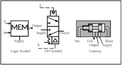
A normally closed, double-pilot-operated 3-way element with only one output is also available to perform the same function as a flip-flop.
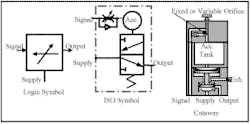
The symbol in Figure 19-6 shows how a flip-flop is represented schematically and the cross-sectional view shows one manufacturer's configuration. Note that this type uses differential pilot areas so the valve can be reset when there is a set signal present.
Time-delay elements
In air logic control there are several different types of time delays. Fixed or adjustable time delays are common in both on delay (or normally closed) and off delay (or normally open) configurations. Some time delays use a fixed or variable orifice and an accumulator chamber to produce delays as long as one minute. Some types use air-actuated diaphragms and orifices to eliminate inaccuracies due to supply pressure fluctuations. (Most types depend on guesses or stopwatch setting procedures.)
One-shot element
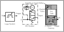
The symbol and cross-sectional view in Figure 19-7 is for a one-shot timer (also called an impulse generator.) A one-shot timer takes a signal at A and passes it on to the circuit. At the same time, input signal A goes through an orifice to an accumulator tank. The setting of the orifice and size of the accumulator tank gives a certain time delay before the normally open 3-way valve under the accumulator tank is piloted closed. After a one-shot times out and closes, it remains closed as long as the input signal at A stays on.
The symbol in Figure 19-7 shows an adjustable time delay. Leaving off the sloping arrow in the symbol makes it a preset non-adjustable time delay. Times range from one half second to two or more seconds on valves with preset time delays.
Many circuit designs use one-shots to eliminate opposing signals. When a valve receives a signal to shift, the opposite pilot signal has no effect until loss of the first pilot signal. A one-shot element drops the first signal shortly after initiation, thus making the valve ready to accept the opposite signal. One problem is that if the short-duration signal meets a hard-to-shift valve, the time period may not be long enough to move the valve spool. When the valve does not have time to shift, the cycle stalls. For best results, add a flip-flop to drop an unwanted signal after it performs its task
Time-on delay element
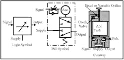
Figure 19-8 shows an adjustable, normally closed time-on delay symbol and cross-sectional view .A time-on delay passes a signal through the element after timing stops. The symbol without the sloping arrow is a preset, fixed time-on delay. Most anti-tie-down circuits use a fixed time delay to force the operator to actuate two palm buttons concurrently.
The symbol in Figure 19-8 shows supply air going to the blocked port of a 3-way directional valve. A signal also goes through a fixed or variable orifice to fill an accumulator tank. After the accumulator tank fills, pilot pressure shifts the 3-way valve to allow supply air to pass to the next operation. If the input signal stays on, the output stays on.
With an integral accumulator tank, time delay length is usually around one to one-and-a-half minutes. With added external accumulators, time delays up to five minutes are possible. The repeatability of long time delays using accumulators is poor. Diaphragm-type timers often go to three minutes with good repeatability.
With a normally open 3-way valve in place of a normally closed 3-way, valve, the timer becomes a time-off delay. Figure 19-9 shows the symbol and cross-sectional view for a time-off delay element. A continuous input to the supply port gives an output until a set time after receiving a signal. The input signal starts to fill the accumulator tank through a fixed or variable orifice and when it is full, it closes the normally open 3-way valve and exhausts the signal.
Time-on and time-off delays often are identical in appearance. Checking the part number may be the only way to tell these units apart.
Air logic valve combinations
To get different functions, connect air logic elements together like the examples in Figures 19-10 and 11. They illustrate two common pairs that might be familiar to anyone using air or electronic logic.
A NAND output, Figure 19-10, uses an AND to signal a NOT. As long as there are no signals at A and B, air passes. If signals are present at A and B, the NOT closes and exhausts the output signal. The term NAND comes from the phrase: not A and B.
A NOR element, Figure 19-11, uses an OR to signal a NOT. When there is no signal at A or B, air passes through the NOT element. If a signal is present at either A or B, the NOT closes and exhausts the output signal. The term NOR comes from the phrase: not A or B.
Other air logic components:
Amplifiers detect low-pressure signals (as low as a 3-in. water column) and send them on as an 80-psi signal. They can be used with gap sensors to detect whether a part is breaking an air-bleed signal.
Pressure or vacuum sequence elements shift after reaching a set pressure or vacuum level. They can be used to indicate an actuator has completed its stroke. They should not be used when the actuator positively has to finish its task before the next operation starts.
Air-operated indicators show circuit conditions and/or functions. Several colors are available, but none emit light.
Example circuit
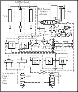
The drill circuit in Figure 19-12 uses most of the components discussed in this chapter -- plus other valves from other parts of this book. For safety, this circuit requires both of the operator's hands to be on the palm buttons simultaneously before a part can be clamped and drilled.
When the operator pushes Start 1 and Start 2 palm-button-operated, normally closed 3-way air valves, they send a signal to the AND1 and OR1 elements. One OR1 output goes to the N.C. time delay and it starts timing. At the same time, both signals from the palm-button valves satisfy AND1, so it sends a signal through NOT2 to the flip-flop to start the cycle. The output from NOT2 also goes to NOT1 and closes it. This keeps the N.C. time delay (which will time out in 0.5 to 1.0 sec) from sending a signal to block the start signal from AND1 to the flip-flop. When the flip-flop shifts, it sends a signal to A+ to start the clamp extending. The same signal also goes to LV1, where it is blocked. When the clamp reaches the part, it mechanically shifts LV1.
After the clamp cylinder extends fully, pressure in its rod end drops the inlet pressure to Start 1. If the operator still had the palm buttons depressed, the loss of air at Start 1 would be the same as releasing that button. Releasing either Start 1 or Start 2 causes AND1 to stop sending a signal to NOT2, which drops its signal to the flip-flop and to NOT1. When NOT1 loses its signal, the N.C. time delay sends a signal through NOT1 to close NOT2, thus preventing a later signal from the palm buttons through AND1 from giving another start signal. This same scenario also requires the operator to let up on both palm buttons anytime they are not depressed simultaneously within a 0.5- to 1.0-second delay. Now the anti-tie-down circuit also is anti-repeat.
LV1 sends a signal to start all three drills on their drill cycle. When the drills leave their home positions, they put out a signal that goes to AND2, AND3, OR2, and OR3. When AND2 and AND3 receive all three drill signals, they send a signal to the flip-flop that shifts it back to its home condition. Its output now goes to the inlet of NOT3. Any or all of the outputs of OR1 and OR2 hold NOT3 shut.
The three drills continue forward until they finish their operations. They then retract automatically (as commanded by their own internal valves). As each drill reaches home position, it drops its run signal to OR1 or OR2. When all drills have retracted fully, NOT3 opens and sends a signal to A- to unclamp the part.
Air logic controllers
To simplify circuit design and troubleshooting, most manufacturers of air logic components now offer a combination of elements in one control module. These units combine a flip-flop, an AND, and an OR element in one component. The symbols in Figure 19-13 show the parts and their arrangement in a single module. One module is required for each signal to and from a circuit. This means for a 3-actuator circuit, there must be at least six logic controllers. These controllers stack and lock together in a row and they have end closures with supply, start, and cycle-end connections.
The first controller in the row receives the start signal that shifts a memory element. The memory element sends a signal to one port of an AND element and an output to the first actuator's air-piloted directional control valve. It also goes to an OR element that sends a reset signal to the start circuit or to the previous controller The first actuator strokes and makes a limit valve at the end of its stroke that sends a return signal, indicating the action has taken place. The actuator's return signal satisfies the other port of the AND, which signals the next module to start the next sequence. This scenario repeats until the end of cycle when the last AND output indicates the controller is ready for another start signal.
The circuit in Figure 19-13 shows the simplicity of an air logic controller setup for the drill circuit in Figure 19-12. It also shows how other logic elements may still be needed to tie common functions together.
Drill circuit using air logic controllers
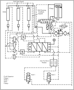
The circuit in Figure 19-14 pictures another way of controlling the drills using air logic controllers and multi-function modules in place of all air logic modules. The machine functions the same as previously described, but there are fewer connections to make and less circuit design skills involved. For this circuit, some logic elements still were required because the drills' feedback is not from switches. A NOT element passes a signal when the clamp cylinder is retracted at the end of the cycle.
When the operator depresses the Start 1 and Start 2 palm buttons simultaneously, an output from the anti-tie-down module starts the first logic controller and it sends a signal to the clamp cylinder's directional control valve to extend the clamp. When the clamp fully extends and makes limit valve LV1, LV1 sends a signal back to the controller's first section which drops the clamp extend signal and starts the controllers second section.
Output from the second section of the controller starts the drills extending. As they begin to move, they send signals to two ANDS and two OR elements. After all drills start, the two AND elements send an output to the second controller, dropping the drill-start signal and starting the third controller.
Output from the third controller goes to the NOT2 element, which is being held shut by signals from the drills through any or all of the OR elements. When the last drill has fully retracted, the signal blocking NOT2 drops out and the third controller sends a signal to the clamp's directional control valve to retract it.
Air from the cap end of the clamp cylinder has been holding NOT1 closed and will do so until the clamp fully retracts and pressure drops in its cap end. When pressure drops in the clamp cylinder cap end, NOT1 opens and signals the third controller to drop its output and send a signal back to the first controller that the cycle is complete. (A limit valve could have been used in place of NOT1.)
(For more air logic circuits, see the author's second Ebook: "Fluid Power Circuits Explained.")
