Cylinders, fluid power motors, and rotary actuators
Fluid power actuators
Fluid power actuators receive fluid from a pump (typically driven by an electric motor). After the fluid has been pressure, flow, and directionally controlled, the actuator converts its energy into rotary or linear motion to do useful work. Cylinders account for more than 90% of the actuators used in fluid power systems for work output. Of the approximately 10% of actuators that produce rotary output, more than 90% are hydraulic motors, while the rest are some form of rotary actuator.
Single-acting ram cylinders
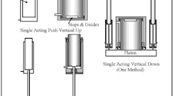
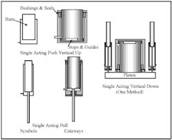
The symbols and cutaway views in Figure 15-1 show single-acting ram cylinders in push and pull types. Rams can be as small and simple as a service station lift operated by air over oil, or as big and complex as a 100,000-ton extrusion press.
Single-acting rams often are mounted vertically up and are weight returned. When a ram cylinder is mounted vertically down or horizontally, it must have some method of retracting it to the home position. Figure 15-1 shows one method. Small single-acting pull rams -- mounted alongside the large working ram -- raise and hold it in the up position with a counterbalance valve (not shown). A directional valve or a bi-directional pump directs fluid to the push or pull rams to make them cycle. Another retraction method uses single-acting push rams that oppose the platen movement from the opposite side. (For a circuit that uses a large-diameter vertical down acting ram cylinder, see Figure 10-9.) Small ram cylinders may be returned manually or via a spring.
Ram cylinders only have seals where the ram passes through the body. Anytime a ram cylinder drifts from its stopped position, the cause is valve or pipe leakage if no fluid is coming out around the ram seal.
As the ram moves, stops and guide protrusions on it keep it aligned and indicate maximum stroke. Usually on large-area rams, the stops tear off the packing gland and bushing retainers if the ram is not stopped some other way. Most machines using rams have other methods to keep them from overstroking. (Some only have warning placards about problems if the ram is powered beyond certain limits.) The guide protrusions and bushing align the ram in its housing so it runs true.
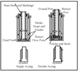
Figure 15-2 shows another type of ram cylinder. When there is a need for a long-stroke actuator with a short retracted length, one option is a telescoping cylinder. Although the majority of telescoping cylinders are single acting, double-acting models are available. Most telescoping cylinders stroke slowly and cycle infrequently because their construction is not robust enough for high production applications.
The cutaway views and symbols in Figure 15-2 depict typical multi-stage telescoping cylinders. The one on the left is single acting; the one on the right is double acting.
Single-acting telescoping cylinders are usually mounted vertically with the small ram up. The cylinder then can be weight returned. This arrangement leaves the large ram with its ports attached to a stationary machine member.
Double-acting telescoping cylinders can be mounted vertically with the small ram down or horizontally when required. The best mounting position for any double-acting telescoping cylinder is with the small ram attached to a stationery machine member so the ports do not move. Long-stroke double-acting telescoping mounted horizontally need some sort of carrier to support the center section during extension so they will not sag and wear out seals and bushings prematurely. Also note: the return area may only be only 10% of the extend area, so the return force is not capable of doing much work. This small area also requires very little fluid to give maximum retraction speed without excessive backpressure at the extend port. Another possible problem with double-acting telescoping cylinders occurs if the retract port is blocked while the cylinder is trying to extend. Up to a 10:1 intensification can result and the high pressure may damage the housing or rams. Installing a safety relief valve at the retract port may be necessary if this port can be blocked or restricted for any reason.
For all telescoping cylinders, make sure the small ram can do the work required. As a telescoping cylinder starts to extend, the large ram always moves first at a lower pressure. When the first and subsequent rams bottom out, pressure and speed increase due to the decreased ram area. If the small ram produces insufficient force, the unit stops before making a full stroke.
Several suppliers build double-acting pneumatic telescoping cylinders in small sizes, with up to three stages.
One manufacturer makes a single-acting telescoping cylinder with internal porting and matching areas that cause all rams to move in unison as they extend and retract. These cylinders come in a maximum of three stages because the area staging would make any more rams into a vastly oversized package. An integral combination check and relief valve allows the rams to be filled and bled and to stroke fully in case of bypass at the seals. This design’s main advantage is smooth extension and retraction without the bumps of a typical telescoping unit.
Piston-and-rod cylinders
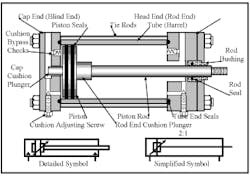
The cutaway view and symbol in Figure 15-3 is for a typical industrial-grade tie-rod cylinder. This cylinder includes all the standard features available from most manufacturers. The names of the parts are what most fluid power glossaries propose, while the names in brackets may be in common use.
The cap end and head end seal off the tube ends with tube-end seals. Tie rods hold the assembly together. The tie rods are tightened to a torque that will resist as much as five times the cylinder’s rated pressure. Tie-rod construction gives the package some flexibility or stretch without permanent deflection or damage. The piston provides the area for fluid to work against. The piston seals stop bypass that would waste energy. The piston rod transmits the force on the piston to the outside of the envelope and is attached to the work mechanism. The rod bushing and rod seal keep the rod aligned and stop fluid leaks to atmosphere. Cap end and rod end cushion plungers block high fluid flow near the end of stroke to allow smooth, no-shock stopping. Cushion-adjusting screws make it possible to adjust stopping speed, while cushion-bypass checks let the piston move rapidly as the cushion plungers are leaving their chambers.
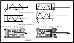
The symbol on the left is the detailed symbol for a hydraulic cylinder with adjustable cushions on both ends. This cylinder also could be as shown as: non-cushioned, cushioned rod end only, or cushioned cap-end only. (When the energy triangles at the ports are blackened, the cylinder is pneumatic.)
The simplified symbol shows less detail but represents the same unit. The 2:1 information over a single rod end cylinder indicates that the rod area is half that of the piston. (Cylinders with 2:1 area ratio will be discussed later in this chapter.)
The spring return and extend cylinders in Figure 15-4 illustrate another method of moving cylinder pistons and rods for some applications. The cutaway views show typical construction (using a tie-rod cylinder as the basic unit). Many other designs are available but essentially use similar parts. Notice that the pistons have mechanical stops to keep the spring from compressing enough to bottom out. Breather ports for air operation or connections for tank drains for hydraulic cylinders are commonly found at the spring end. Most manufacturers indicate that the spring is only capable of returning the piston and rod. It may not be capable of returning the external load. Springs can be less than reliable and difficult to monitor -- especially when they are internal. Because there usually is little savings in hookup or operation, use these cylinders with care.
Tandem cylinders
The tandem cylinder in Figure 15-5 can produce almost twice the force from the same diameter, but it is a little over twice the length. The two cylinders can be independently piped or drained to give extra force in one direction only or both directions. The center heads have guide bushings and seals for both sections so a different fluid can also be used in either end. (See Chapter 17 to learn how tandem cylinders allow oil to control speed and air as the power source. Circuits for matched and unmatched tandem cylinders can be found in the author’s upcoming e-book Fluid Power Circuits Explained.)
The tandem cylinder in Figure 15-5 has a common rod for both pistons. The tandem cylinder in Figure 15-6 has two separate pistons and rods and two different stroke lengths. This combination can be used to get three positive stops from an air or hydraulic cylinder with no special valves or controls. The stops are mechanically fixed, so the stop positions are in the same place every time. However, the stop positions only work for one situation. A four- or five-way directional valve at each cylinder plus flow controls are all that is normally required to operate this circuit.
Special consideration must be used in circuit design for the unattached tandem cylinder in Figure 15-6. If the long-stroke cylinder is not restrained while the short-stroke cylinder extends, it can overtravel and miss the exact position. This problem is exaggerated with horizontal or vertical rod-down applications. Meter-out flow controls or counterbalance valves can eliminate the problem, but could increase cycle time in some cases.
The cap-to-cap mounted cylinders in Figure 15-6 depict another way to use pneumatic or hydraulic cylinders to obtain positive positioning without special valves or equipment. Two four- or five-way valves and flow controls usually make this circuit operate smoothly.
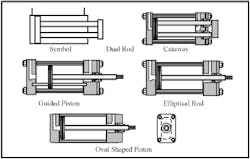
Some designers specify double-rod end cylinders such as those shown in Figure 15-7. These cylinders cost about twice as much as single-rod cylinders and the design has a second place for fluid to leak. In most cases the reason for using them can be accomplished by other methods with equal or better results. If you must use a double-rod end cylinder, remember to allow space for the extra rod and the safety hazard it can cause. Also, the rod reduces the area on the working side of the piston, so a larger bore or higher pressure is necessary in many cases.
A double-rod end cylinder might be specified so that the force and speed in both directions is the same when flow and pressure are equal. This may be true, but flow controls and a reducing valve can accomplish the same result at a reduced cost and in less space. Another alternative is a regeneration circuit, used when producing the exact speed and force in both directions is not critical. (Regeneration circuits are covered extensively in the author’s upcoming e-book Fluid Power Circuits Explained.)
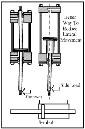
It may appear that double-rod end cylinders reduce rod flexure when the cylinder is fully extended. The rods in their bushings and the piston in its bore provide snug bearing points -- but allow some play. As the piston nears the end of stroke, two of the bearing points get closer together, so lateral movement at the extended end of the rod can increase. It is supposed that the opposite rod will reduce lateral movement and hold the attached load closer to a centered position. However, from the cutaway it is obvious the distance between the piston bearing and the opposite rod bushing almost eliminates any centering effect of the piston. A better way to reduce lateral movement of the extended rod is to stop the piston short of full stroke – either by an internal stop tube or externally by machine members. This arrangement requires a longer cylinder but gives the desired results at a lower cost.
A main reason for using double-rod end cylinders is to mount limit switches to show cylinder position. A special bracket opposite the attachment end holds the limit switches and a doughnut-shaped protrusion on the rod contacts them as the piston strokes. For the same price (and consuming a lot less space), most cylinder manufacturers offer limit switches that attach to the head and/or cap and are activated by cushion plungers. Another signal indicator -- especially for pneumatics – is a Hall-effect switch and a magnetic piston to activate it.
All of the above cylinder-position indicators have one potential major flaw. If the part attached to the rod end gets disconnected for any reason, the machine still will cycle when the cylinder moves...even though the disconnected load may be in the way. If at all possible, mount limit switches on the machine member so its position is never misinterpreted.
Non-rotating rod cylinders
The cylinders in Figure 15-8 incorporate some method to keep the piston and rod from rotating as it strokes. A standard cylinder may try to turn as it extends and retracts, causing it to unscrew from its workpiece. In some applications, the cylinder is expected to orient the work piece it is driving and keep it aligned with mating parts. All the designs in Figure 15-8 attempt to accomplish this non-rotating function in different ways. At best they can keep the rod from turning but none can perfectly guide it when outside forces are acting to turn it. This is especially noticeable on long-stroke cylinders. It is always best to guide the workpiece externally and only use the cylinder to cycle it. Note that the oval-piston design offers the ability to mount cylinders side by side with minimum rod center distance between them and still produce ample force.
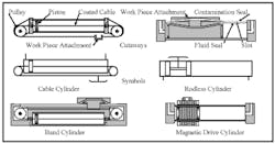
The cylinders in Figure 15-9 take up less space on long-stroke applications because they only need mounting space slightly longer than their stroke length. Conventional piston-and-rod cylinders require space more than twice their stroke length -- and can be difficult to conveniently place on many machines.
The earliest long-stroke design is the cable cylinder – shown at top left in Figure 15-9. A coated cable fitted with a work piece attachment, wrapped around two pulleys, and attached to a piston in a bore produces reciprocating motion as fluid -- usually air -- enters and exhausts through the ports. These cylinders are usually 4-in. bore or less, and may have strokes up to 30 ft (or more in certain configurations). Cushions may be specified when required. The cable is coated with nylon or Teflon so it can slide through seals with minimal damage to them. However, the coatings are prone to cracking and eventually will cut the seals until they leak. (The symbol for the cable cylinder is adapted from a manufacturer’s catalog because ISO does not show one.)
The rodless cylinder, top right in the figure, was introduced in the late 1970s. It is even more compact than a cable cylinder and avoids the coating wear problem. It consists of a piston in a bore that has a slot open to atmosphere along its whole length. A seal blocks air from escaping through the slot while the piston is not present. A second contamination seal keeps debris from filling the slot. The fluid seal and contamination seal pass through slots in the piston in slots as it reciprocates. The work piece attachment (connected to the piston) reciprocates to move machine members as fluid enters and exhausts the cylinder. Bores up to 2 12 in. and strokes as long as 33 ft are available from several manufacturers. Cushions may be specified when required.
The band cylinder is an alternative to the cable cylinder. Its smooth steel band passes through seals instead of a coated cable. The magnetic-drive cylinder uses magnetic attraction to keep the piston and workpiece attachment connected. It operates at pressures up to 120 psi and will maintain connection up to 180 psi.
One manufacturer has a modified rodless cylinder with a toothed belt and pulley arrangement to drive the workpiece attachment. It offers the option of an external output shaft to which a brake can be fitted to stop and hold position. This output shaft can also drive an encoder to show work piece position or can connect to another unit for synchronization. It also could act as a low power rotary actuator. It is available in 1- or 1 12-in. bores and up to 177-in. stroke.
Other types of linear actuators
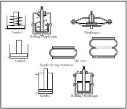
The actuators in Figure 15-10 depict other ways of producing linear force. The rolling diaphragm, diaphragm, and bellows actuators are single acting. The rolling diaphragm is capable of long strokes but not long life at high cycles. The diaphragm is designed only for short-stroke applications only but can have high force due to large areas. All these single-acting devices use some internal or external method to retract them. Using vacuum and weight are two of the methods used for retracting bellows. The double-acting rolling diaphragm operates like a double-acting piston cylinder but is not designed for long life at high cycles.
Because most cylinders are round, the formula for figuring their area that most remember is: π r2. Another formula for circle area is .7854 D2 which does not require changing to radius before figuring area. There are also data books that have charts for all standard size cylinders. To determine maximum cylinder force, multiply the known area by the operating pressure in psi. The standard formula is written F=PA where F is force, P is pressure and A is area.
For pneumatic cylinders, the usual working pressure is 80 psi even though most plants cycle their air compressor between 115 to 125 psi. The reason for the lower working pressure is because line losses, especially during high flow surges, make it impossible to maintain compressor output pressure over the entire air supply system.
Operating pressure for hydraulic circuits often falls between 1500 and 2500 psi because most components are rated at 3000 psi. Lower pressures require larger actuators at higher flows and over-sizes the entire system. Pressures over 3000 psi often require special components and are usually relegated to very high force applications.
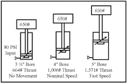
A factor that is often overlooked when sizing cylinders, especially pneumatic ones, is the force figured by the aforementioned formula is not available until after reaching full pressure. A pneumatic circuit does not reach full pressure quickly like a hydraulic circuit does. For example, when tank pressure is high and tire pressure is low it is easy to rapidly fill a flat tire from a portable air tank. However, as tire pressure starts approaching tank pressure, pressure drop decreases and the transfer rate slows to a crawl as rising tire pressure gets closer to lowering tank pressure. Pressure equalization can take several minutes, adding to cycle time when the tire is an actuator. The 3 1/4-in. bore air cylinder in Figure 15-11 will not move the load attached to it because force required and force available do not allow enough pressure drop to move fluid from inlet to the piston. The 4-in. bore gives nominal speed while the 5-in. bore would give fast speed.
To get nominal cycle times, always size air cylinders at least 25% above workforce whether moving a load or applying force. When cycle time must be fast, oversizing up to 100% could be required. Anything above 100% will quickly lessen the effect and is not worth the expense.
Even with hydraulic cylinders, pressure buildup may be fast but is not immediate. Oversizing of 10% is usually enough to achieve reasonably fast cycles in most situations. Other things that slow hydraulic actuator cycle time and pressure buildup include trapped air, slow shifting valves or valves with long spool overlap, and using pressure-compensated pumps without an accumulator.
Typical cylinder seals
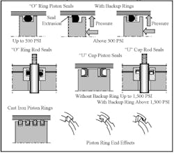
The cutaways in Figure 15-12 show the standard ways of sealing pistons and rods from fluid bypass. O-rings and U-cups are resilient and continuous seals that can stop all fluid bypass so a cylinder can be stopped and held almost indefinitely. Cast-iron piston rings do not seal completely but do a good job when system shock or high heat is part of the operation.
O-ring seals are inexpensive but do not have long life in most applications. They must be setup with interference so as they wear they continue sealing. This also adds to breakaway and running friction. They are bi-directional and should not be used in pairs. With two O-rings on a piston, fluid can bypass and get trapped between the seals causing a lot of friction. At pressures above 500 psi, always specify backup rings to keep the O-rings from extruding and being damaged. Always keep O-rings well-lubricated because they can stick and roll in their cavity. When they start rolling they wear rapidly.
U-cups are long-life, low-friction seals because their flexible lips can be heavily preloaded without much increased friction. These seals are pressure energized, which means pressure inside the “U” forces the seal material tightly against the sealing surfaces. U-cups usually use backup rings at pressures above 1500 psi to keep them from extruding.
Material for the resilient seals discussed here is commonly Buna N rubber for pneumatics and many hydraulic cylinders. When synthetic fluid or high heat is encountered, resilient seals often are made of Viton. Buna N is good for temperatures up to 250° F with mineral oil and water glycol. Viton works at temperatures of 400° to 450° F and any fluid used in air or hydraulic circuits. Other seal materials such as leather, Neoprene, and Teflon are available and are standard for some suppliers.
Automotive-type cast-iron piston rings in sets of two or four seal well but not completely. A general rule is that they will leak approximately one cubic inch per minute per inch of bore per one thousand psi. Different end effects have been designed to reduce leakage at the expansion joint. Placing the expansion joint 180° from each other for consecutive rings helps slow leakage.
Cylinder cushions
Cylinders that move at high speed need some sort of deceleration method to keep them from slamming when they reach end of stroke. Some applications with high speed and heavy loads may need valves and limit switches to give enough time to bring the load to a smooth stop. For most cases standard cylinder cushions work well. They are 3/4- to 11/16-in. long and can be in the head or cap end or both. Cushions add cost on most cylinders so should not be specified when unnecessary.
Hydraulic cylinder cushions
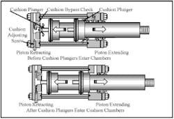
The cutaway in Figure 15-13 shows a cylinder with an oversize rod and standard cushions on both ends. The cushion-adjusting screw and cushion bypass check valve can only be installed in the cap end because the cushion plunger on the rod end is so large there is no room for them. The necessity of oversize rods is a problem for most manufacturers. It is possible to taper the cushion and get a smooth stop but it also slows the stroke as the cushion plunger leaves its chamber. The best option to control deceleration of oversize rod cylinders’ extend stroke is with external valves or proportional directional controls.
The other problem with oversize rods and rod-end cushions is the high intensification pressure present when working pressure is high and/or there is a heavy overrunning load. Pressure in the rod end can easily reach two-to-four times rated pressure each time the cylinder extends. High pressure can damage tube end seals and piston seals, and stretch the cylinder tube past its tensile limits.
The top cutaway in Figure 15-13 shows the cylinder piston moving to end of stroke with full flow exiting through the cushion chambers almost unrestricted. This means the cylinder can travel fast until the cushion plungers enter their chambers. The bottom cutaway is what happens after the cushion plungers have entered the cushion chambers. Trapped fluid decelerates the piston quickly to a speed set by the cushion-adjusting screws. Deceleration is sudden on the straight cushion plungers shown here because hydraulic fluid is almost non-compressible. The piston continues to end-of-stroke at a preset controlled speed without damage to itself or the machine.
On cylinders with standard and some oversize rod sizes, the rod-end cushion would function the same as one on the cap end. There is always some pressure intensification on the rod end but this is normally not a problem. When the cylinder starts to extend again, the cushion bypass check valve opens to allow fluid to the full piston area so it can extend quickly at full force. Without the bypass valves, takeoff speed would be as slow as deceleration on retract.
The cutaways in Figure 15-13 show a way of making cushions work. In actual cylinder design, cushions are built in many ways but the general function is the same. One company offers a self compensating non-adjustable cushion option without adjusting screws or bypass checks. Another supplier offers tapered or tapered slots in the plungers that give smooth deceleration instead of the sudden slowdown. Tapered cushions only work for a given pressure, load, and mounting position. They must be figured from information collected prior to building the cylinder.
Pneumatic cylinder cushions
Pneumatic cylinder cushions have similar designs but operate differently because the fluid is compressible. When the cushion plunger enters a cushion chamber, the trapped air starts compressing according to Boyles’ Law discussed in Chapter 1. When the load is light and the starting trapped pressure is high enough, the cylinder stops smoothly without slamming. When the load is heavy and/or starting trapped pressure is low, the cylinder slows but still may bang the end of stroke. This situation requires the addition of external deceleration in the form of valves and/or shock absorbers. Often the rod cushion is ineffective due to less area for the trapped fluid to work against. As with hydraulic cylinders, oversize rods exaggerate the problem.
Most suppliers offer standard cushions on both air and hydraulic cylinders. This option could smooth the operation of certain heavy loads that need extra deceleration distance. These longer cushions only work well for a fixed load and speed condition. If the machine has changing loads and/or speeds a cushion is not the way to go. Using external shock absorbers or proportional valves makes control easy to setup.
Cylinder rod column strength and buckling
Most cylinders are designed to have ample rod strength regardless of mounting style to rated pressure and strokes to 20 in. Above 20-in. strokes, standard rod size may be too small to keep it from bending in compression. Some mounting styles are more prone to buckling problems and need special attention. When an order is placed for cylinders with long strokes that operate above certain pressures, cylinder suppliers usually offer engineering help on design changes and/or rod modifications. Most cylinder catalogs have formulas and/or charts that show how to figure rod column strength for different mounting styles. In many cases the life of a cylinder is dependent on cylinder mounting type and rod size.
Another problem encountered in cylinder design is with bearing loads. A cylinder has bearing points at the rod and its bushing and the piston in the bore. Neither area is strong enough to carry external loads such as a machine member or other parts. Always use the cylinder to push and pull -- not as a guide.
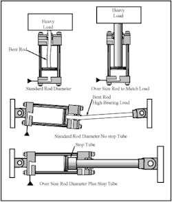
Figure 15-14 shows column strength and bearing load problems on long stroke cylinders and how to overcome them. The vertical cylinder at top left with the heavy load does not have a large enough rod to lift it. When pressure is applied the undersized rod will bend and the load will not move. If the load does move, rod flex soon wears the bushing and allows leakage. Matching rod size to load and pressure makes a workable design.
The lower horizontally mounted long-stroke cylinder with a standard rod has two problems -- column strength and high bearing loads. The weight of the cylinder as the cylinder extends wears on the bearing points and high force will finally bend the rod instead of moving the work. The oversize rod on the lower, horizontally maintained cylinder is sized to handle the load at maximum force but does little to help bearing load problems.
Adding a stop tube to the piston rod keeps the bearing points farther apart and reduces wear. Notice the overall package is longer now because the stop tube takes up space inside the cylinder. Always check out bearing side-loading problems before building the machine. It can be difficult to fit the longer stroke cylinder or more costly to constantly change rod bushings and seals.
Cylinder mounting styles
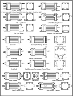
The mounting styles shown in Figure 15-15 depict the standard NFPA-approved ways to mount cylinders. Up to 25 different companies make cylinders that match these styles in every dimension. This means no supplier has to be the sole source for any cylinder on a machine. Starting at top left are the least expensive mounting styles. Tie-rod mounts are extensions of the tie-rod threaded section. These extensions go through a machine member with nuts installed and tightened to hold the cylinder in place.
The standard offerings are designated two tie rods extended both ends, MX4, four both ends, MX1, four cap end, MX2, four head end, MX3. At best, these mounting styles hold a cylinder in place but not necessarily in a precise location. They should only be considered when what they are attached to does not travel a rigid path.
The tapped mount, top right, is another inexpensive mount but may be hard to locate and hold cylinder position. It can create problems on long-stroke cylinders that need to stretch when pressure is applied. With both ends tied down, the cylinder is not free to grow from pressure or external force without binding. They are designated by the MS heading.
The side and end lug-mounted cylinders are another way to rigidly mount a cylinder but also can be a problem on long strokes. The lugs are extra long so dowel pins can be installed after a precise position is determined. It is not good practice to have dowels in both ends of the cylinder or on opposite corners especially on long strokes. They are designated by the MS heading.
Other rigid mountings are flange mounts in rectangular and square style. They are designated by the MF and ME headings. The bolt-on flanges are for light-duty operation or where the flange is in compression. The extended head and cap flanges are extremely heavy duty and directly replace the bolt on flanges.
The most versatile mounting styles are pivot mounts. They allow freedom of movement in one or both planes and keep the cylinder in perfect alignment. The intermediate trunion is very good on long stroke applications since cylinder weight can be balanced and reduce bearing loads. Care in choosing cylinder mounting style can add years to its life and eliminate rod seal leaks for long periods. Interchangeable NFPA tie-rod design cylinders come in bore sizes of 1 1/2, 2, 2 1/2, 3 1/4, 4, 5, 6, 7, 8, 10, 12, 14, 16, 18, and 20 in. Rod sizes available are 5/8, 3/4, 1, 1 3/8, 1 3/4, 2, 2 1/2, 3, 3 1/2, 4, 4 1/2, 5, 5 1/2, 7, 8, 9, and 10 in. The largest rod diameter for any bore is equal to or slightly under half the area of the piston. This is commonly known as a 2:1 area ratio cylinder. Oversize rods give fast return at low force, allow for regeneration of rod flow, and allow for higher push force capabilities due to greater column strength. Many manufacturers make cylinders in smaller and larger bores but they are not necessarily interchangeable.
Steel mills often use what are called mill cylinders that have bolted-on heads and caps. They are special to a machine in most cases with little or no interchangeability. Mobile equipment uses cylinders with welded heads and caps that are designed to be thrown away when they fail. However, many repair shops cut them apart and repair them. Mobile cylinders also have screwed-on heads or special snap ring arrangements in their assembly.
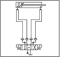
The cylinder in Figure 15-16 has such a small diameter and is so far from the directional valve that the lines to and from it hold more fluid than it does. In this situation fresh filtered fluid never cycles through the cylinder so it overheats and all wear particles and rod ingestion stay in it until it fails. Failure is always premature and the amount of contamination present is excessive when it is repaired. Changing the lines to the dual flow path shown in Figure 15-16 eliminates the contamination problem. Cylinder operation and longevity is greatly increased because filtered fluid constantly flushes it.
A tee is installed at A and B ports and check valves facing opposite directions are placed at each end. Separate lines run from the check valves to a tee at each cylinder port. Now all fluid must go to the cylinder through one line and return through the opposite one. Fresh fluid is continually being fed to the cylinder while used fluid returns to be cooled and filtered.
The dual flow path circuit is more important when the cylinder is mounted vertically with long lines. Contamination in this configuration lays on the piston and seals and can score cylinder tube and cause premature seal wear when allowed to collect.
