Fluid power pumps
A fluid power system’s prime mover is a pump or compressor that converts electricity or some form of heat energy into hydraulic or pneumatic energy. These devices can be rotary or reciprocating, single or multiple stage, and fixed or variable volume. They may move a variety of fluids and come in many different designs. Some pump designs offer unique features that make them especially suitable for a particular application.
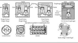
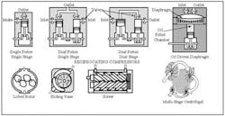
Figure 8-1 shows several types of compressors in simplified cutaway form. These cutaways represent many standard designs used in industrial applications. They are not complete representations but simply show general working principles.
Reciprocating-piston air compressors
The single-piston/single-stage, dual-piston/single-stage, and dual-piston/dual-stage compressors illustrated in Figure 8-1 are typical designs for piston-type air pumps. Compressors of these designs may be rated as low as horsepower or as high as 1000 or more horsepower. The smaller sizes are air cooled while larger ones are water cooled.
Single-stage compressors normally operate at 125 psi or less and produce approximately 4 scfm (standard cubic feet per minute) of flow at 100 psi. (One scfm is 1 ft3 of gas at 68°F, 14.69 psia, and a relative humidity of 36%.
Diaphragm air compressors keep lubricating fluids out of the air or gas they are compressing. This arrangement often makes the air suitable for breathing and it can be used in applications where contamination from compressor oil cannot be tolerated. The cutaway view in Figure 8-1 shows an oil-driven diaphragm compressor that is capable of very high pressure. As the oil piston extends, it forces oil against the diaphragm to compress the gas. On the retract stroke, pressure inside the diaphragm plus vacuum returns the bladder to pick up more atmospheric air.
Piston-type reciprocating compressors below a 15- to 25-hp range usually start and stop at preset low and high pressure settings. Larger reciprocating compressors typically continue to run after pressure reaches the preset maximum, but they then stop compressing by holding their inlet valves open. This arrangement is called unloading. It saves wear on the electric motor because the motor only has to start one time.
Rotary compressors
Rotary compressors employ lobed rotors, vanes, screws, or impellers to draw in ambient air and compress it. Figure 8-1 also shows these devices. While these types of air pump are more compact and produce less vibration, they have lower efficiency than other types. All these designs (except the multi-stage centrifugal compressor) are limited to a maximum of 150 to 200 horsepower.
Rotary compressors run continuously and are capable of no flow to full flow at any time. An inlet-restricting valve closes or opens in response to pressure changes. Many rotary compressor installations do not require a receiver tank, due to their ability to change flow in relation to demand.
Pneumatic pump efficiency
Using atmospheric air as a means to transmit energy is very inefficient. A 1-hp air motor requires between 7 and 15 compressor hp while it runs. A hydraulic motor that produces the same output would only need 1½ to 2 hp input.
Air cylinders are more efficient than air motors, but still require three to four times more prime mover energy than their hydraulic counterparts. The general rule of thumb is: use hydraulic cylinders when an air-cylinder circuit would require a 4- or 5-in. or larger bores to produce the necessary force. This is especially important when the cylinders must operate at high cycle rates. Up-front cost of the hydraulic system is more, but operating cost savings soon pay for the added expense.
On the other hand, a 20-in. bore air cylinder used to maintain tension on a conveyor belt (with minimal cycling) would be a very efficient system.
Complete air compressor installation
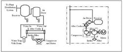
Figure 8-2 combines the schematic diagram and picture representation of a typical air compressor installation. (The compressor could be a reciprocating or rotary type.) The aftercooler may not be required on installations under 50 hp, and it could be air-cooled instead of water-cooled. An air dryer is necessary in certain applications, but is often left out due to added cost. As noted earlier, a receiver tank might be eliminated with a rotary compressor is there never is a demand for short bursts of high-volume air. Water traps with drains are required on all systems because a compressor takes in a lot of water with the ambient air. (Even with an air dryer there is always the time when the dryer needs service but the system cannot be shut down. A trap will help during these times.) Other components, such as isolation or bypass valves for the aftercooler and air dryer, often are part of the circuit.
Hydraulic pumps
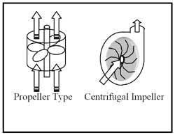
Most hydraulic pumps are positive-displacement devices. Pumps with positive sealing parts -- whether rotary or reciprocating -- move fluid every time they operate. This means that if the pump is turning, it produces flow. (Conversely; blocking flow stops the pump’s rotation mechanically.) Positive-displacement pumps have higher efficiencies than their non-positive-displacement counterparts, such as impeller or centrifugal designs. Figure 8-3 illustrates some non-positive-displacement designs that could be used to run hydraulic circuits. Because these pumps only run at 50 to 75% efficiency, they are not used in high-pressure circuits. They are frequently found in systems with high-water-content fluids (HWCF), such as 95% water and 5% soluble oil, because these pumps require little or no lubrication. Also, these systems usually operate at or below 400 psi.
Some positive-displacement pumps are paired with centrifugal pumps to pressurize their inlets to keep them from cavitating. Or, when a positive-displacement pump is run at higher rpm than specified, the inlet may not be large enough to let in enough fluid at atmospheric pressure. In this case a non-positive-displacement pump can force fluid into the undersized inlet and eliminate cavitation.
A non-positive-displacement pump does not require a relief valve in many installations. There is enough slippage in most designs to allow for stopping flow while not over pressuring the circuit. However, if the pump operates at no flow for more than two or three minutes, simple bypass circuit to move fluid for cooling purposes should be added. The bypass circuit could be a small relief valve, a manual petcock, or a normally closed solenoid valve operated by a timer or pressure switch.
The propeller design is the least efficient of these pumps because there is a direct path from inlet to outlet through the blades. The minimum rpm of this type pump is high due to this open path. The centrifugal-impeller design operates at much closer tolerance so it slips less fluid while operating.
Fixed-displacement pumps
Fixed-displacement pumps are found most commonly in circuits with a single actuator. This allows the pump to be unloaded at little or no pressure when not performing work. A multiple-actuator circuit, where only one device moves at a time, can also be practical for fixed-displacement pumps if the actuators use about the same volume of fluid. This means total pump flow is either doing work at load pressure or is being sent to tank at very low pressure.
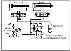
Avoid using meter-in or meter-out flow controls with fixed-volume pumps because a flow restriction increases pressure and the increase sends fluid to tank at the relief valve setting. This produces excess heat and all the problems associated with it. One way to use fixed-displacement pumps with multiple-actuator circuits is to include an accumulator with an unloading and dump valve. With this circuit, the pump is only on pressure when fluid is required. The accumulator accepts excess pump flow and provides working flow when the pump is unloaded. Figure 8-12 shows a fixed-volume pump with an accumulator.
Fixed-displacement pumps are usually less expensive and more contamination tolerant than pressure-compensated pump. Note: this does not mean they should be run with dirty fluid or that cheaper is really less expensive. It only means they fill the bill in many applications where cost is a factor.
Gear-on-gear fixed-displacement pumps
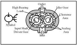
One of the oldest hydraulic pumps is the gear-on-gear design shown in Figure 8-4. As the driven gear turns, the idler gear turns in the opposite direction. At first, air trapped between the teeth and housing is moved to the outlet and forced out by the meshing teeth in the center. This starting action creates a negative pressure (vacuum) at the inlet. Atmospheric pressure then pushes oil into the pump. Now hydraulic fluid flows around the teeth and out to the circuit. Because the sealing action -- between the gear teeth and the housing, and where the teeth mesh -- has minimum clearance, when fluid is blocked, the gears stop turning.
A standard gear pump is unbalanced because there is high pressure on one side and low pressure or vacuum on the other side of the gears. This causes high bearing loads and shortened service life at pressures above 1500 psi. Some newer designs reduce this unbalance by clearing the housing (or clearance area) and only having a short sealing area. This greatly reduces bearing forces so that pressures up to 4000 psi continuous are commonplace today. However, even with this new design there is no compensation for gear or housing wear.
Gear-on-gear pumps can have more than one pumping section within a common housing. This allows for different flows or pressures to some circuits for speed and force changes.
Internal-gear fixed-displacement pumps
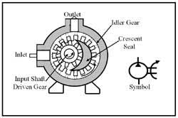
Figure 8-5 shows a cutaway view and the symbol for an internal-gear pump. The standard design is unbalanced and has no way to compensate for tooth or housing wear. Most pumps of this type are limited to 1000 psi or less. They are often used as transfer or supercharging pumps at low pressure due to their less efficient design. (There is a German-designed internal-gear pump that has a wear-compensating feature and a special bearing arrangement that allows it to operate continuously at up to 5000 psi and with more than 95% overall efficiency throughout its life.) Standard gear pumps start out at 85 to 90% efficiency when new. As the gears and housing wear, their efficiency deteriorates until they no longer supply enough fluid to maintain cycle time.
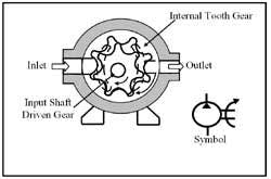
The newest design of a gear pump is called a gerotor (combining the words generated and rotor). A cutaway view and symbol is shown in Figure 8-6. This pump design is not common in the marketplace. At present there are only one or two manufacturers that offer this type. On the other hand, as a fluid motor it is one of the most common designs and is offered by more than 15 different companies.
A gerotor pump uses a driven gear of, say, seven teeth inside an internal-tooth gear with eight teeth. The driven gear rotates inside the internal tooth gear and they both turn in the same direction. Because of the machined shapes, the driven gear always makes contact with the internal tooth gear at different points as they rotate. As the example in Figure 8-6 shows, this allows cavities to open and close as the gears turn.
In the example, as the driven gear turns clockwise, the internal tooth gear turns the same direction, but at one tooth per revolution slower speed. This action causes cavities to form on the left hand that start reducing pressure in this area. This reduced pressure (vacuum) allows higher atmospheric pressure to push fluid into the pump and fill the forming cavities. Kidney-shaped cavities in this sector, on both sides of the teeth, accept fluid to fill them for 180° around the inlet side. As the gears continue to turn, the cavities formed on the left side start closing on the right hand side. This forces fluid through the kidney-shaped openings and to the outlet port.
Like other gear pumps, gerotor pumps are unbalanced and have no way to compensate when clearances become worn. Although a new gerotor pump starts out at 85 to 90% efficiency, it deteriorates as it runs and constantly loses volume.
Gerotor pumps also can have more than one pumping section in a common housing, again allowing for different flows or pressures to some circuits for speed and force changes.
Another point on gear pumps: their output flow cannot be varied -- except by changing them physically or running them at a different speed. The next two types of pumps are capable of changing volume while running the same speed. These pumps can also reduce flow on a pressure build-up signal and almost eliminate the need for a relief valve.
Multi-screw fixed-displacement pumps
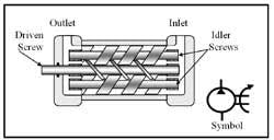
The pump in Figure 8-7 is similar to a gear pump but uses helical gears or screws to move the fluid. The driven screw is in close fit mesh with the idler screws and all gears have minimum clearance in the housing. As the driven screw turns, the idler screws also turn and the cavities between the screws move toward the outlet. This action forms a vacuum at the inlet. Atmospheric pressure then pushes fluid into the cavities and the fluid moves to the outlet. This pump has very smooth flow -- without the pulses produced by the other positive-displacement pumps in this manual. Flow from the outlet is smooth and continuous. However, screw pumps are not highly efficient. There is a lot of bypass in the original design and as the screws and housing wear, bypass increases. This design pump often is used to supercharge other pumps, as a filter pump, or a transfer pump at low pressure.
Vane-type fixed-displacement pumps
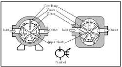
The most common pump for industrial applications is the vane design shown in Figure 8-8. The left-hand cutaway view illustrates the original unbalanced design. Today, most vane pumps are of the balanced design shown on the right. Balanced vane pumps operate at higher pressures and have long bearing life. All vane designs compensate for wear, so their efficiency stays in the 90 to 95% range throughout their service lives. Vane pumps are efficient, quiet, and inexpensive. They have great longevity when supplied with clean fluid.
As a prime mover turns the rotor, centrifugal force slings the vanes outward. (Most manufacturers recommend a minimum speed of 600 rpm to make the vanes extend.) Now, as the vanes follow the off-center cam ring, a chamber is formed between the cam ring and the rotor. This chamber gets larger as the vanes extend, creating a negative pressure (vacuum) at the inlet port. Atmospheric pressure then forces fluid into these enlarging voids and fluid starts to move. As a vane passes the highest point on the cam ring, it is forced back into its slot and the chambers between the vanes decrease. As a chamber size decreases, fluid is forced out through the kidney-shaped openings to the outlet. Even though vane tips wear, they still touch the cam ring, so efficiency is not affected for a long time.
The other leakage and wear point is at the sides of the gears or rotors of these pumps. Most modern vane pumps have pressure-loaded floating plates that are hydraulically forced against the turning members. Hydraulic pressure tries to push the plates away from the gears or rotors in a certain area, but a slightly larger area on the opposite side of the plates pushes back under the same pressure. This keeps the side areas sealed without applying excess force against the turning members. (Some inexpensive low-pressure pumps may not have floating side plates but depend instead on manufacturing tolerances to control leakage.)
Vane pumps are available with two or three pumps in one housing to give more flow or different rates of flow to satisfy the needs of some circuit designs. These pumps have a common inlet and separate outlets as required.
Typical circuits for fixed-volume pumps
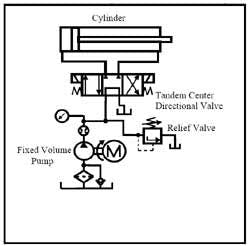
Figure 8-9 shows a circuit using a fixed-volume pump in a simple, single-cylinder circuit. A tandem-center directional control valve routes all pump flow to tank at low pressure when the cylinder is idle. When the cylinder cycles, pressure never goes higher than necessary to do the work at hand, so energy waste is minimal. With an efficient pump, this circuit operates all day without a heat exchanger and fluid temperature never increases more than 10° or 15°F above ambient.
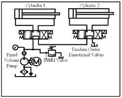
Use caution when selecting directional valves for this circuit. Pay particular attention to pressure-drop charts because pressure drop is additive for each valve. This circuit could start up with a 200-psi drop at idle. With more valves in series, pressure drop at idle and running can cause sluggish operation and generate heat. Also, choose valves that are able to operate at tank line pressure. Every upstream valve sees pressure at pump and tank ports while a downstream actuator is working.
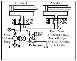
Figure 8-11 shows a multiple-cylinder circuit that uses a normally open solenoid-operated relief valve to unload the pump when the actuators are idle. Anytime an actuator cycles, a solenoid on its directional control valve and the solenoid on the normally open solenoid-operated relief must be energized at the same time. This circuit often requires flow controls -- and may need a heat exchanger to get rid of wasted energy.
The circuit in Figure 8-12 has a fixed-volume pump with an accumulator to store energy and allow the pump to unload when no fluid is required to do work. It is similar to a pressure-compensated pump circuit because there is only pump flow at pressure when the circuit calls for it. The pump-unloading-and-accumulator-dump valve sends pump flow to the circuit until pressure reaches its set level. After reaching set pressure, the valve opens fully and dumps all pump flow to tank at minimum pressure. When circuit pressure drops about 10 to 15%, this valve closes and again directs pump flow to the circuit. (A normally open solenoid-operated relief valve controlled by a pressure switch could be used in place of the pump-unloading-and-accumulator-dump valve.)
Pressure-compensated, variable-volume vane pumps
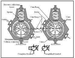
Figure 8-13 shows cutaway views and symbols for a pressure-compensated vane pump. Vane pumps are one type of fixed-volume pump that can be made to function as variable volume and/or pressure compensated. The pumping action is the same as the fixed-volume, unbalanced vane pump previously discussed. The difference is that the cam ring is not fixed but can move in relation to the rotor. An adjustable force spring holds the cam ring in its offset position until enough pressure builds inside it to push against the spring and drive it toward center. As the cam ring moves closer to center, output flow decreases until it finally stops. The cam ring never makes it all the way to center because some flow is always needed to make up for internal bypass.
Internal leakage in fixed-volume pumps passes into the case and back into the inlet flow. Internal leakage in variable-volume pumps also passes into the case but has no passageway to return to the inlet line. All internal leakage must be drained from the case directly to tank through a full-flow drain line. This case-drain line should exit from the highest point on the pump so the case stays full of fluid at all times. Always fill the case of a newly installed pump to make sure it has lubrication at startup. Also, make sure the case-drain line terminates below fluid level in the tank so it cannot suck air.
Some pressure-compensated pumps have a maximum-volume adjusting screw to prevent the cam ring from going to full stroke. This feature makes it possible to adjust the maximum flow when pressure is below the compensator setting. The feature could be used to limit maximum horsepower when only a small portion of a higher flow pump is required. (In most circuits this feature has no use because flow is usually controlled by flow controls or actuator size.)
Two symbols can indicate pressure-compensated pumps schematically. The complete symbol on the left shows all the functions, while the simplified symbol on the right omits the case drain and shows the compensating arrow inside the pump circle. Because most schematic drawings now are done on CAD systems that automatically produce the complete symbol, the simplified symbol seldom appears today.
Pressure-compensated pumps normally do not need a relief valve to protect the system from over pressure. However, many circuits with pressure-compensated pumps use a relief valve just in case the pump hangs on flow. When a relief valve, for whatever reason, is used with a pressure-compensated pump, it is imperative that it be set 100 to 150 psi higher than the pump compensator. If the relief valve is set lower than the compensator, the circuit will operate as a fixed-volume setup and quickly overheat the fluid. If the relief valve is set at the same pressure as the compensator, it is possible that the relief valve will start to dump at the same time the compensator starts to reduce flow. Then the pressure drop lets the relief valve shut and the compensator asks for more flow. These oscillations can continue until the pump fatigues and fails.
Setting the relief valve and compensator is a four-step operation.
- Set the relief valve at maximum pressure.
- Set the pump compensator at a pressure that is 200 to 300 psi higher than final system pressure.
- Set the relief valve 100 to 150 higher than the final compensator setting.
- Set the pump compensator at system pressure.
The other reason often stated for using a relief valve in a pressure-compensated pump circuit is because of pressure spikes. When a pressure-compensated pump has to instantaneously shift from full flow to no flow, fluid leaving the pump while it is shifting to center has no place to go. Because pressure is resistance to flow and resistance is a maximum at this point, pressure can climb very high. These full-flow to no-flow spikes can easily go as high as five to seven times the pump compensator setting (depending on the pump volume). Adding a relief valve to this scenario can reduce the spikes because a relief valve will respond much faster than a pressure-compensated pump. However, a pilot-operated relief valve still has some response time and will often spike two to three times its setting before opening fully.
A better way to protect the pump and circuit is to install a small accumulator at the pump outlet and pre-charge it to approximately 80% of set pressure. Now when the pump must react rapidly, the accumulator provides a place for excess fluid to go. An accumulator also helps actuator response time at cycle start because there is a ready supply of fluid even though the pump is at no flow.
Piston-type, fixed-displacement pumps
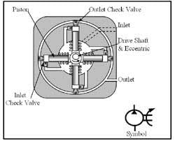
There are two types of piston pumps in use today. The oldest design is the radial-piston type. Radial-piston pumps come in two different configurations. The one shown in Figure 8-14 is sometime called a check valve or eccentric pump. The design in Figure 8-15 is what usually comes to mind when radial pumps are mentioned.
The cutaway in Figure 8-14 shows how the pistons move fluid when the eccentric turns and strokes them forward, while springs return them. Check valves at the piston ends allow flow from the inlet chamber and exit flow to the outlet port.
Many of these type pumps are capable of very high pressures -- up to and exceeding 10,000 psi. At the same time they usually flow low volume -- below 6 gpm. They are highly efficient pumps, with unidirectional flow. In fact cw or ccw shaft rotation produces the same flow rate and direction. (An eccentric pump can be made pressure compensated and/or variable volume by restricting inlet flow or pressurizing the area under the pistons to keep the springs from fully extending them.)
Variable-displacement radial-piston pumps
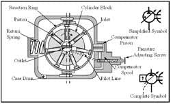
Figure 8-15 shows a cutaway view of a basic radial-piston pump that can function as fixed volume, variable volume, pressure compensated, and bidirectional flow, or a combination of these functions. The pump in Figure 8-15 is variable volume only. As a fixed-volume pump it would have the reaction ring offset as shown in the right hand cutaway view, with no method of changing that condition. (This is one configuration that will probably never be used with this design pump.)
As the cylinder block and pistons rotate, centrifugal force pushes the pistons against the reaction ring. When the pump is in the on-flow condition (as in the right-hand cutaway view), the pistons are moving out of their bores in the lower half of the picture and forming a vacuum. Fluid is forced into the inlet and fills these voids. As the pistons pass left center, they stop extending and begin to be pushed back into their bores. During the top half of their travel, the pistons force the trapped fluid through the outlet to the circuit. Moving the reaction ring’s centerline closer to the cylinder block’s centerline reduces flow
Pressure-compensated, radial-piston pumps
The radial-piston pump in Figure 8-16 is pressure compensated. This pump produces flow when the outlet pressure falls below the level set by the pressure-adjusting screw. When pressure in the pilot line increases enough to compress the compensator spool’s spring, pilot flow is connected to the compensator piston, and its drain to the case is blocked. Pilot flow to the compensator piston forces the reaction ring to move against the return spring and reduce outlet flow. The reaction ring never reaches center because the circuit, pilot control, and internal leakage must be overcome to hold pressure.
Two symbols can be used to show pressure-compensated pumps schematically. The complete symbol at the lower right of Figure 8-16 shows all the functions, while the simplified symbol above it omits the case drain and places the compensating arrow inside the pump circle. Again, because most schematic drawings are done on CAD systems now, the simplified symbol is seldom used.
A radial-piston pump can also produce bi-directional flow. It can take in or force out fluid from either port while turning the same direction. This design pump is used in closed-loop circuits where all outlet flow goes to an actuator and return flow from the actuator goes back to the pump inlet. A common circuit of this type is a hydrostatic drive. Fluid from a bi-directional pump goes to a bi-directional motor to give infinitely variable output speed and force in either direction of rotation without requiring a directional control valve.
Bi-directional, radial-piston pumps
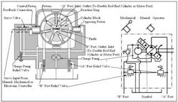
The pump in Figure 8-17 has a small opposing piston that pushes continuously against a larger control piston on the opposite side of the reaction ring. The control piston can be pressurized or exhausted by a 3-way servovalve, thus infinitely varying the reaction ring position to either side of center. Input signals to the servovalve can come from manual, mechanical, or electronic controllers. A common circuit produces four manually variable flows and directions, using four single-solenoid directional control valves.
A charge pump, driven off the main pump shaft, supplies pilot oil to maintain pressure on the opposing piston. It also supplies oil to the mechanical-feedback servovalve that pressurizes or exhausts the control piston. The charge and pilot circuits usually run at 250 to 400 psi. Notice that the “A” and “B” ports are only connected to the actuator -- not to tank -- when using a hydraulic motor or double rod-end cylinder. (The pump must have added tank ports to operate a single rod-end cylinder circuit.)
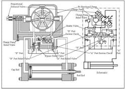
Figure 8-18 shows a cutaway view and schematic drawing of a bi-directional pump driving a single rod-end cylinder. Because there is less volume in the rod end of a single rod-end cylinder, flow to and from that end is less in relation to the cap end. This poses a problem when using a closed-loop circuit.
The pump cutaway and schematic show how adding suction check valves, a shuttle valve, and a bypass relief valve allow the pump to bypass excess flow from the cap end and take in added flow for the rod end. This is a common circuit for this type pump. With this circuit, cylinder speed is infinitely variable and direction change requires no directional control valve. Direction change is very smooth because flow must go to zero in one direction before it can reverse. Because of this, the actuator rapidly and smoothly decelerates to a stop condition. When flow reverses, it increases steadily to full flow in the opposite direction without system shock.
