Poppet-type directional control valves
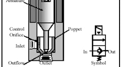
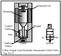
Poppet-type directional control valves are similar to pilot-to-close check valves. The cutaway view in Figure 10-15 shows the construction of a hydraulic 2-way, normally closed, poppet-type directional control valve. Fluid at the inlet port passes through the control orifice to the backside of the poppet. The tip of the spring-loaded armature closes off the outflow orifice to trap fluid behind the poppet. As the symbol shows, the valve is a check valve that stops flow from inlet to outlet in the normal condition. This design will not stop flow from outlet to inlet, although flow in this direction may be at a reduced rate. If using this valve for reverse free-flow in its normally closed condition, make sure to choose one with free-flow capability.
Energizing the solenoid coil creates a magnetic field that raises the armature to open the outflow orifice. This orifice is larger than the control orifice, so the greater flow through it causes a pressure drop behind the poppet. Now, inlet pressure pushing on the poppet’s annulus area outside the seat diameter unseats it to allow fluid flow to the outlet. De-energizing the solenoid coil lets spring force reseat the armature tip to again trap fluid behind the poppet and close it.
Unlike spool valves whose lands overlap, poppet valves open a flow path to outlet immediately. This means response time of whatever the valve controls is very fast. Also, when a spool valve shifts open it goes to the end of its stroke regardless of the amount of flow. On the other hand, a poppet only opens as much as the flow going through it needs. This means the poppet has less distance to move to stop flow, so again its response is faster.
Chapter 11 covers poppet-type slip-in cartridge valves used for directional control. These valves have the same characteristics as just explained here and they work well in circuits that require fast response. Chapter 12 covers infinitely variable spool valves that also offer very fast response.
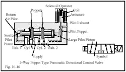
The 4-way poppet valve in Figure 10-16 is a typical design for pneumatic service. Poppet design valves are very tolerant of contamination and many plants use them for this reason. They are also very responsive and provide a positive seal when their poppets seat. (Many poppet valves are built with resilient materials on the poppets where they contact the seats.
One drawback to this design is that air is free to go any direction as the poppets shift from one flow path to the other. In valve terminology this is called open crossover (and can be helpful with hydraulic valves as explained later). The cutaway view in Figure 10-16 shows how flow can go to both cylinder ports and to both exhausts as the poppets move to the opposite seat.
Another possible problem with poppet valves is that they usually only operate in one manner. When you purchase a 2-way, normally closed poppet valve, it cannot be changed to normally open. The port marked In is always the supply line. Air piped to the Out or Cyl port usually blows through the valve with little resistance. Spool-type valves (discussed next) overcome these problems in most cases.
The poppet valve in Figure 10-16 shifts to its second condition when the coil of the solenoid operator receives an electrical signal and pulls the armature up. This action lets supply air into the large pilot piston to move the poppets to the second valve position. Even though the small pilot piston has supply air against it all the time, it has less force. De-energizing the solenoid operator exhausts the large pilot piston and the poppets return to the normal position.
This is a very reliable design because there are no springs to rust, weaken, or break. Usually the area ratio is 2:1; so shifting force is equal in both directions. Some manufacturers also use a spring in the return end to keep the poppets in place when there is no air supply. Valves with this type of shifting arrangement usually require a minimum pressure of 25 to 40 psi or an external pilot supply at least that high.
Spool-type directional control valves
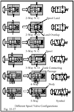
For circuits with flows less than 100 gpm, the most common hydraulic directional control valves use a spool-like internal member to direct flow. (Many air valves also use a spool, due to the advantages offered by this design.) The cutaway views in Figure 10-17 show some simplified spool arrangements and terms associated with this valve. Notice that counting the number of ports that carry working fluid on the cutaway or symbol gives the number of ways the valve has. A 2-ported valve is a 2-way valve and a 5-ported valve is a 5-way valve.
All valves in Figure 10-17 are two position as shown by two boxes in the symbol. As stated before, a 2-way valve can have only two positions because it can only stop or allow flow. All other valves are able to have three positions, while 4-way valves can have four positions in special cases. A 5-way valve is a special case mainly used in pneumatic applications where an extra exhaust port is not a problem. Notice that a 4-way valve has five ports but its tank ports are internally connected to eliminate an extra port in the body. This is important in hydraulic valves because it reduces piping and potential leak points.
The main advantage of spool valves is that fluid entering the valve from any working port does not affect spool movement. The poppet in a poppet valve can have pressure on one side and only a light spring on the other. This can result in premature movement of the poppet when pressure enters a port. In a spool valve, pressure always is applied to two equal opposing areas or the edge of a land. Thus pressure forces that could move the spool are cancelled or non-existent. This means that a spool valve can be shifted manually, electrically, mechanically, pneumatically, or hydraulically with the same force regardless of the operating pressure. Low-force solenoids can be used because the most they need to overcome is mechanical friction and light springs.
Spool valve disadvantages
Many spool valves are designed with metal-to-metal sliding fits. As a result, some fluid may bypass these seals. If this happens, an actuator may not hold its position if outside forces are applied. It also means wasted energy and resulting heat. (Many pneumatic valves use some sort of resilient seal in the body and/or on the spool to eliminate air leaks.) To reduce bypass, spool valves have land overlap, so as they start shifting to open a flow path, there is a delay before fluid starts flowing. The delay only lasts for milliseconds and does not cause a problem -- unless the cycle is very fast and/or there are several valve shifts per cycle.
Another time delay occurs when a spool shifts to the end of its stroke. There is often more movement than required for the flow needed. When the spool shifts back to center or to the opposite flow path, it consumes more time to travel the extra distance. This slows the cycle, especially when several valves are involved. Stroke limiters that control maximum spool movement can eliminate this delay, but are seldom seen in actual practice. The common fix for these problems is to speed up traverse time by installing a larger pump. However, faster actuator movement can add shock and heat due to higher energy input.
Hydraulic 4-way spool valves
Most manufacturers of hydraulic valves only build a basic 4-way function. When they offer a 2-way function, it is usually a 4-way valve with a different spool and the unused ports plugged or piped to tank. Any 4-way valve can perform 2- or 3-way functions in a normally closed or normally open configuration by using the right ports and plugging or draining unused ones.
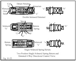
Hydraulic 4-way valves usually come in 2- or 3-position configurations. They may be 2-position, single-solenoid, spring-return; double-solenoid, detented; or 3-position, double-solenoid, spring-centered. Some manufacturers offer 4-position valves with a float or regeneration center position for special circuits, but they are rare.
The majority of hydraulic circuits use a 4-way, 3-position directional valve even though it complicates the electrical circuit. One reason may be to provide the ability to stop an actuator in mid cycle -- either for manufacturing or setup functions. Other reasons are to port pump flow to tank while the machine is idling or to let external forces move an actuator.
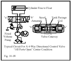
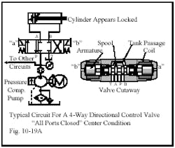
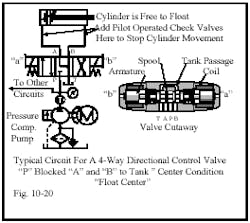
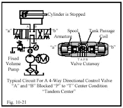
Figures 10-18 through 10-21 show typical circuits in schematic form with valve cutaways for the four commonly used center conditions in hydraulic 4-way directional control valves. (Symbols for other spool center conditions are shown in Chapter 4.) Each center condition offers a flow path to meet a specific circuit need that should be obvious when reading a schematic. Note that these typical circuits are not the only way to apply these valves.
The circuit in Figure 10-18 uses an all-ports-open center-condition valve that allows flow to and from all ports. Notice how the spool lands are too narrow to block the fluid ports. This means fluid is free to go to other ports while the spool is centered. The symbol for the valve plainly shows this open-center condition. A circuit with this type of valve normally has a fixed-volume pump. The open center lets all pump flow return to tank at little or no backpressure. This saves energy and reduces heat to the point that a heat exchanger is not necessary on most circuits.
The cylinder in Figure 10-18 is free to float when acted on by outside forces. Otherwise it sits still. Normally this circuit only has one valve and actuator. Other valves and actuators trying to use this pump would not receive fluid due to the free path to tank.
The valve in Figure 10-19a has an all-ports-closed center-condition that blocks pump flow. This valve appears to be able to stop and hold a cylinder in place. Notice how the spool lands are wide enough to completely cover the A and B ports. This blocks flow to and from them, and also stops flow at the P port. This circuit normally has a pressure-compensated pump. System pressure is at the pump compensator setting until all pump flow is going to the actuators at their working pressures. The pump in a closed-center circuit can supply other circuits one at a time or simultaneously with low to medium energy loss -- even when operating at less than maximum flow.
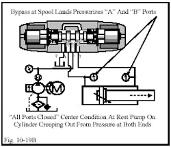
Because all metal-to-metal fit valves have some spool bypass, a closed-center valve will not stop and hold a single-rod cylinder except for a short period. Figure 10-19b shows how bypass fluid at the spool lands leaks directly into the A and B ports and pressurizes both ends of the cylinder at roughly half system pressure. Equal pressure at both ends of a single-rod cylinder always causes it to extend due to unequal forces on unequal areas. The cylinder will not move rapidly because some fluid must go to tank across another leak path. This cylinder action is called regeneration, and will be explained under cylinders in Chapter 15.
In a new circuit, bypassing fluid may not affect the cycle, but it can cause problems later on. Also, cylinders with small rods and/or heavy loads may not have enough force to move -- especially when machine fits are new and tight. The actual force in this regeneration mode is calculated by multiplying the rod area by pressure at the cylinder cap end.
The circuit in Figure 10-20 shows a float-center valve. The P port to the pump is blocked, and ports A, B, and T are interconnected so that both cylinder ports are open to tank. Notice that the spool lands are wide enough to block the P port but still allow flow to or from A and B ports flow to or from each other or tank. A pressure-compensated pump normally supplies a circuit with this valve. System pressure is the pump compensator setting until all pump flow is going to the actuators at their working pressures. The pump in a float-center circuit can supply other circuits one at a time or simultaneously with low to medium energy loss, even when operating at less than maximum flow.
When a cylinder in a multi-actuator circuit must be positively locked in place, select a valve with a float-center condition, and add pilot-operated check valves or a counterbalance valve. (Adding these blocking valves to an all-ports-closed-center directional control valve often does not prevent cylinder movement.)
With a float-center valve a single-rod cylinder may extend at any speed when the circuit has high tank backpressure. High tank backpressure goes to both ends of the cylinder and causes it to extend if the load is low and/or the cylinder has an oversize rod. To overcome this situation, install a check valve at the T port to stop back flow from the tank line.
On horizontally mounted cylinders, use pilot-operated check valves in the cylinder lines to positively lock the cylinder from moving due to external forces. On vertically mounted cylinders, use a counterbalance valve to hold the load and keep it from running away while cycling. (Counterbalance valves are explained in Chapter 14.)
The circuit in Figure 10-21 uses a valve center condition with the A and B ports blocked, and the P connected to T. This valve lets pump flow go to tank and blocks both cylinder ports. This configuration is often referred to as a tandem-center valve. Notice that the spool lands are wide enough to block the A, B, and P ports – the same as an all-ports-closed valve. However, this valve has a hollow spool and cross-drilled ports at P and both ends at T. The drilled passages provide a path for all pump flow to go directly to tank in the center position. Because the drilled passages also introduce extra backpressure, most suppliers’ catalogs show a lower nominal flow or higher pressure drop for tandem-center valves.
Circuits with tandem-center valves normally have fixed-volume pumps. The pump-to-tank path lets all flow return to tank at little or no backpressure. This saves energy and reduces heat to the point that a heat exchanger is unnecessary in most circuits. Be aware of the reduced flow or higher backpressure when specifying or using tandem-center valves. A circuit may look good on paper, but can run hot because of wasted energy. This is especially true when using tandem-center valves in series. The backpressure for each valve is additive. A three-valve circuit can easily require more than 300 psi to unload the pump.
Most 2-position valves are found in circuits with pressure-compensated pumps because they block flow when an actuator stalls. When actuators need pressure continuously, a 2-position valve simplifies the electrical control circuit. A momentary signal shifts a double-solenoid detented valve to its other position and the valve stays there until it receives the opposite signal. A single-solenoid spring-return valve must have a maintained electrical signal to stay shifted. This solenoid setup causes all actuators to return to home position at the loss of control circuit power or after an emergency-stop signal.
Single-solenoid spring-return or double-solenoid detented valves are commonly used in air circuits because pressure is always available and blocking flow does not cause overheating.
