Hydraulic filters
Contaminated fluid causes most hydraulic system failures. Oil in a reservoir may look clean to the naked eye, but silt contamination particles too small to see can still wreck pumps, cause valves to stick, and erode cylinder bores. In many facilities, components may take the blame for problems in error, when contaminated fluid is the culprit. It is amazing that some plants will change pumps every six months (believing that is normal component life), when they could add a proper filtration system and get many times longer pump service life.
A well-filtered hydraulic system should not have particles in the fluid larger than 10 microns. (A micron is 0.000039 inches.) A contamination particle that measures 0.001 in. across is 25 microns. The smallest dirt particle that is visible to the naked eye is 40 microns. Simply looking at an oil sample is not a good way to tell if the filters are cleaning the fluid.
Nominal or absolute are common terms found in hydraulic filter micron ratings. A filter with a nominal rating takes out most of the particles that measure the same size or larger than the stated micron size. A filter with an absolute rating takes out all particles the same size or larger than the rated micron size. A newer filter-rating system called the beta ratio is replacing the old nominal and absolute designations.
The beta ratio indicates what size particles the filter removes, followed by the ratio of the number of this size particle in the fluid upstream from the filter, divided by number of particles that size in the fluid downstream from the filter. For example: a filter rating of beta 5 = 90 indicates the filter will remove 90 of every 100 particles of 5 micron or larger size from the fluid passing through it. The efficiency of this filter would be 98.9% -- or 100 - (100/90).
Most hydraulic filters employ a closely controlled paper fiber mat or a woven wire mesh element to trap particles. While woven wire is more expensive than paper, the ability to manufacture it with more precisely sized fluid flow openings makes it a better choice. Also, woven wire elements can withstand higher pressure drops without collapsing.
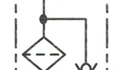
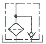
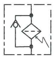
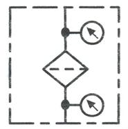
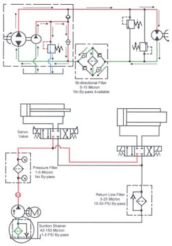
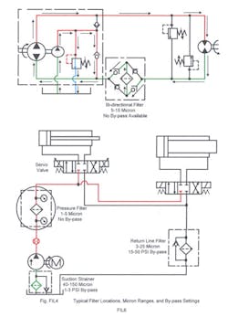
Figures 9-1, 9-2, and 9-3 show the symbols used in circuit diagrams for the common filter types. The hydraulic circuit diagrammed in Figure 9-4 has these filters in typical locations.
Suction strainers
Figure 9-4 shows a hydraulic circuit with filters in standard locations. Strainer is a common name for filters with openings of 75 microns or larger. Suction strainers usually are installed in the pump inlet line to protect the pump from large, damaging contamination particles that can cause catastrophic failure. The suction strainer also protects the pump from ingesting any start-up debris left in the tank and piping. In addition, the suction strainer traps large contamination particles introduced to the system from external sources or resulting from internal part failure.
Don’t use filters with low-micron ratings in suction lines because pumps without supercharged inlets can only tolerate a portion of one atmosphere pressure drop without affecting inlet flow. With this low-pressure drop (14.7 psi maximum, at sea level on an average day), a restriction such as a low-micron filter can cause the pump to cavitate. Cavitation will cause pump failure almost as fast as dirty oil, so avoid it in every situation.
Suction strainers are normally available with openings ranging from 75 to 150 microns. Some manufacturers offer inlet filters with ratings as low as 25 microns. These low-micron elements have large filtering surfaces.
If the pump is force-fed by another pump (sometimes called a supercharge pump), use of a low-micron rated element is possible. The supercharging pump will force fluid through a very fine filter to the working pump without cavitation.
A suction strainer or filter should have a bypass relief valve. Set the bypass to open at a pressure of 1 to 3 psi when the strainer becomes clogged. The reasoning behind this is that the pump will run many hours on contaminated oil, but will fail in a few minutes with little or no oil.
Suction strainers can be located inside or outside the reservoir. Internal strainers are less expensive, but their condition is more difficult to monitor. External strainers are easy to service and often include an indicator to show when the filter starts bypassing. The indicator can be as simple as a vacuum gauge or it might be a vacuum-operated electrical output to a warning light or controller.
Many older circuits have nothing but a suction strainer for filtration. Retrofitting these systems with the off-line or kidney filters discussed later in this chapter is advisable.
Return-line filters
Another common location for filters is in the return line. (See the circled item in Figure 9-5.) The return-line filter keeps most contamination caused by part wear from getting into the tank. These filters are offered with ratings ranging from 3 to 25 microns. A common level of filtration is 10 microns. Obviously, if the desired system cleanliness is 10 microns, use a filter of 10 microns or less.
Return-line filters should have integral bypass check valves. If the filter becomes loaded, return oil needs a flow path to tank until it is convenient to change the filter. Without a bypass, the filter element may collapse, or the element housing or seal may rupture. The bypass check valve usually requires 10 to 50 psi to open. The bypass pressure should be high enough to stop fluid from going around the filter except under unusual conditions, but low enough to keep the filter element and housing seal from being damaged.
Sizing return-line filters just to handle pump flow is a common practice. However, sizing the filter to pump flow can cause problems if cylinders in the circuit have oversized rods, or if one cylinder returns one or more other cylinders. For example, if a cylinder has a 2:1 rod diameter, flow to tank while the cylinder is retracting will be twice pump flow. Sizing the filter just for pump flow will allow contaminated oil to bypass at least -- and may damage the housing or seals. Paper filters can collapse, have holes blown through the element, stop filtering, and never indicate they need to be replaced. With pleated elements, the pleats can collapse, giving a premature “loaded element” indication.
Even with a correctly sized return-line filter, the flow through it changes constantly. A steady flow through the element gives the most efficient filtration. If a filter passes constant flow, the bypass valve will not open until the filter fills with contaminants. This means only clean fluid leaves the filter.
Visual and electrical indicators also are available to show when the return-line filter is bypassing.
Pressure line filters
Servo directional control valves normally require pressure-line filters because these valves have low contamination tolerance, as shown in the lower circle on Figure 9-6. These valves have small internal orifices, very close-tolerance fits, and must shift rapidly at low pilot-pressure differential. A servovalve can stop functioning in as little as two minutes with oil from a typical hydraulic system. Any servovalve circuit operates best with a pressure filter.
Even when a 3-micron return-line filter is installed, contamination generated by the pump is enough to shut down a servovalve in a short time. To solve this problem, place a pressure filter in the line between the pump and the servovalve. To eliminate servovalve contamination in circuits with long lines, place a pressure filter at each valve inlet.
Pressure-line filters normally have elements with 1- to 5-micron openings. The pressure filter should be of the absolute-rated type, or have a beta ratio of 50 or higher.
A pressure-line filter should not have a bypass. If the filter element clogs, it is better to stop flow to servovalves than to contaminate them. Indicators on the filters warn of clogging to allow the elements to be changed before production speed is affected. Visual and electrical clogging indicators also are available for most pressure-line filters.
Pressure-line filter housings must be strong enough to withstand full system pressure. When there is a high pressure drop across the filter, the element must not collapse. These requirements make pressure-line filter housings and elements more expensive than return-line filters. High cost is the main reason for not using pressure-line filters on all systems.
Figure 9-6 pictures a bi-directional pressure-line filter. Another name for this bi-directional filter is "last-chance filter." Because it is in the working line to an actuator, this filter has to withstand maximum system pressure. The only difference between a bi-directional filter and a standard pressure filter is the four check valves in the housing. The four check valves cause oil flow to pass through filter element in the same direction regardless of the direction that the fluid enters the housing. A bi-directional filter will normally have a 3- to 10-micron rating for most circuits. Pipe a bypass check externally when required.
Closed-loop hydrostatic transmission circuits are one place to use bi-directional filters. Note that the oil between the pump and motor can stay in the loop for long periods. Any contamination in this closed loop will continue to cause damage, even after changing oil in the tank.
Off-line filtration
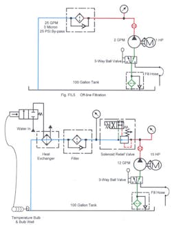
The top image in Figure 9-7 shows an off-line filtration circuit. This is an easy circuit to retrofit to existing hydraulic systems. Also, it is an excellent circuit for new systems where high cleanliness levels are needed. Sometimes called kidney filters or bypass filters, off-line filtration systems consist of a separate pump, motor, and filter that re-circulates oil in the reservoir. Oil from one end of the tank passes through the filter and returns to the opposite end of the tank.
The filter in the off-line circuit should be rated in the 3- to 10-micron range. The circuit should be set up to filter the volume of fluid in the reservoir every 1 to 3 hours minimum. This low, constant flow rate makes the filter very efficient, never opens the bypass, never causes channeling, and never blows holes in the element.
When the off-line filter indicator shows a clogged element, the main hydraulic circuit can continue to run during filter change. Also, this type filter system can operate while the main hydraulic circuit is shut off over nights or weekends.
Always filter new oil before use since it not as clean as most hydraulic systems require. Put new oil into the tank through a pair of shut off valves, or a 3-way ball valve in the suction line (as diagrammed in the bottom of Figure 9-7). Rotate the 3-way ball valve 180 degrees, hooking the pump suction to a flexible hose in an oil drum or fluid container. This set-up filters all oil from the fluid container before it enters the reservoir.
Any circuit with a servovalve still requires a pressure filter downstream from the pump. Also, according to the working conditions, a return-line filter may be helpful to take out system-generated particles before the fluid goes back to tank.
A heating or cooling loop is another function sometimes performed in an-off line filter circuit. Figure 9-8 shows a bypass circuit with a normally open solenoid relief valve, a high-horsepower motor, a temperature switch, a heat exchanger, and a temperature-controlled water valve. These additions can effectively control temperature while filtering the fluid. (To only filter the oil, leave the water turned off and the solenoid relief valve open.) If oil temperature drops too low, the temperature switch will energize the solenoid on the relief valve and pressure will rise. All electric-motor horsepower converts into heat until the temperature switch indicates the correct oil temperature. Unlike an immersion-type electric tank heater, the fluid is being circulated, so there are no hot spots. For every electric horsepower, there will be 2544 Btu/hour heating capacity. After figuring the Btu/hour to heat or maintain minimum temperature, divide by 2544 to calculate the horsepower needed.
If the tank fluid overheats, the temperature-controlled water valve will open, sending water through the heat exchanger. All filtered flow cools while the temperature valve indicates elevated temperatures. The heat exchanger always passes constant flow, so a bypass valve around it is unnecessary. Also, the heat exchanger passes flow even when a pressure-compensated pump in the circuit is holding pressure without flow.
Air-line filters
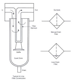
Air-line filters trap debris in air lines to protect downstream valves and cylinders. They also capture condensed water in the air stream. Most air-line filters have a manual drain to get rid of the trapped water. Several manufacturers offer an automatic drain at added cost.
The filter media in air-line filters consists of compressed fibers, ceramics, or sintered metal. A standard air filter removes particles 40 microns or larger. Most manufacturers also can supply filters with ratings as low as 5 microns when required.
Air entering the filter, Figure 9-8, flows along the walls of the bowl to swirl out condensed water – which drops to the bottom of the bowl. The air then passes through the filter media, and on to the regulator and lubricator. A baffle separates the lower part of the bowl, making a quiet zone for trapped water so it won’t be picked up again.
To get even better air quality, coalescing filters are available. Coalescing filters remove up to 99.9% of oil aerosols, as well as particles down to 0.3 microns. These filters are desirable in instrument air and paint spraying applications, or any other circuit that requires very clean air. The basic design of a coalescing filter is the same as a standard filter. The main difference in is the filter element. The filter element is for one-time use and is quite expensive. Most suppliers recommend standard filters upstream to remove larger particles and liquids, thus extending the service life of the expensive coalescing element.
Air filters usually do not come with a bypass check valve. When the filter becomes clogged, flow restriction increases until air flow finally stops. Pressure drops on gauges at the inlet and outlet show when to change the filter element.
