Fluid Motor Circuits
One way to change fluid energy into useful work is through air or hydraulic motors. These fluid motors produce rotary power that can drive conveyors, operate long transfers, power fan blades, run a winch, drill and tap a hole, and handle many other applications.
Compared to electric motors, quick reversal of rotation or stalling does not damage a fluid motor. Changing motor speed (within the limits of its specifications) does not adversely affect torque. Repeated starting and stopping air or hydraulic motors does not cause damage or overheating. Also, hydraulic motors commonly operate at low speed without a gear reducer. These features — along with compact size — make fluid motors the best choice in many applications.
To size a fluid motor, calculate torque instead of horsepower. However, remember that fluid motors have approximately 50% less starting torque than electric motors of the same horsepower. Make allowance for this reduced torque if the motor must start under load.
Vane-design air motors are common in low-torque/high-speed applications. For some high-torque applications, vane motors with integral gear reducers work well. Piston-type motors are larger and more expensive, but they produce high torque at low speeds. A less expensive, more-compact gerotor-design air motor that operates in the lower-speed range also is available.
Air motors operate safely in most environments and save space at the work site. Air motor efficiency is very low — only in the 15 to 30% range. Minimizing run time by starting and stopping the motor helps offset low efficiency in many applications.
Air motor speed varies with load changes. Power level and torque also vary widely with speed change. Without a good silencer or muffler, air motors are loud.
Hydraulic motors, on the other hand, can produce speeds from 1 to 5000 rpm. With proper valving they produce little shock, and their efficiency is in the 80 to 95% range. They also operate safely in most environments and save space at the work site. They are very rugged. Unlike cylinders with resilient seals, hydraulic motors always leak or bypass internally. To stop and hold over-running loads, use a brake or other external device.
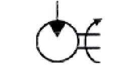
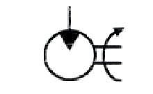
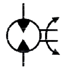
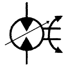
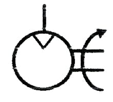
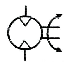
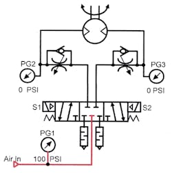
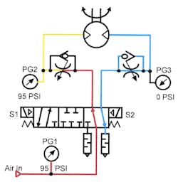
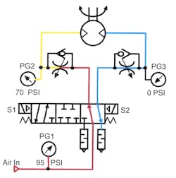
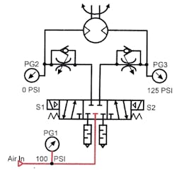
Figure 12-1 and Figure 12-4 show the symbols for a uni-directional hydraulic and air motor. Figures 12-2, 12-3, and 12-5 show motors designed for bi-directional operation. Figure 12-3 shows a variable-displacement bi-directional hydraulic motor symbol.
Sizing a hydraulic motor system
To size a hydraulic motor system, the following information must be known:
1. Maximum torque required (usually in in.- or ft-lb)
2. Maximum speed required (usually in revolutions per minute, rpm)
3. How motor will be stopped (coast, braked, decelerated, other)
4. Maximum pressure allowed (in psi, arbitrarily decided by the engineer or designer)
Sample problem – see Figures 12-6 through 12-9
Maximum torque = 5400 in.-lb Maximum pressure = 3000 psi
Maximum speed = 220 rpm Motor will coast to a stop
Sizing an air motor system
To size an air motor system the following information must be supplied:
| 1. | Maximum torque required | Usually in foot-pounds (or horsepower could be substituted) |
| 2. | Maximum speed required | Usually in revolutions per minute, rpm |
| 3. | How motor is stopped | Coast, braked, decelerated, other |
| 4. | Maximum pressure allowed | Usually 80 to100 psi |
Sample problem – see Figures 12-10 through 12-13
| 1. | Maximum torque required | 10 ft-lb |
| 2. | Maximum speed required | 150 rpm |
| 3. | How to stop motor | Retarded |
| 4. | Maximum pressure available | 90 psi |
Directional controls for hydraulic motors
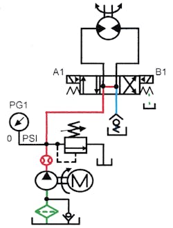
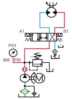
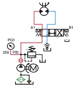
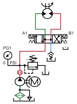
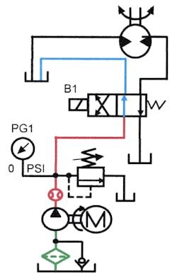
Figure 12-14 shows a solenoid-operated control circuit for a small, uni-directional hydraulic motor. Energizing the solenoid starts and runs the motor. Deenergizing the solenoid allows the motor to coast to a stop. Depending on the type and amount of load, starting and stopping the motor may be anywhere between smooth and abrupt.
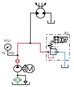
Figure 12-15 shows how to control a large uni-directional hydraulic motor via a normally open, solenoid-operated relief valve. This circuit is less expensive than one that uses a large directional valve and a relief valve. Solenoid-operated relief valves discharge pump flow to tank at about 20 to 50 psi, normally keeping the motor stopped. Energizing the solenoid on the relief valve causes it to start closing. The closing of the relief valve builds pressure and the motor starts to turn. If pressure tries to go higher than the relief setting, this valve stays partially open, which gives the motor time to accelerate. When the motor is at maximum speed, pressure drops, and the relief valve closes completely, directing all pump flow to the motor inlet. If the system pressure tries to go higher than the relief setting, the valve opens to protect the circuit. De-energizing the solenoid on the relief valve allows the motor to coast to a stop without cavitation.
Note that if the motor can turn at the low unloading pressure (20 to 50 psi), it may never stop completely. Use a brake valve at the motor outlet to keep it from turning if this situation occurs.
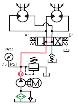
Figure 12-16 shows two hydraulic motors in a parallel circuit. Supplying two or more motors from a single valve lets the fluid follow the path of least resistance. Synchronizing the motors with a flow divider (Chapter 11) or by a mechanical linkage would keep them together. With parallel circuits, all motors have full torque but only get a portion of pump flow. In other words, the motors have equal power at reduced speed.
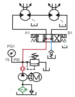
The series circuit in Figure 12-17 has the outlet of the first motor piped to the inlet of the second. This series circuit gives nearly perfect speed synchronization, but reduces each motor’s power.
The series circuit works well with hydraulic motors because outlet flow is almost identical to inlet flow. This near-equal flow provides tolerable synchronization, but generates backpressure on the inlet and outlet ports of the leading motor. All hydraulic motors have some internal leakage that normally goes to the low-pressure or tank-side outlet through internal check valves. With motors in series, backpressure to run the downstream motors can cause excessive case pressure that may blow out the shaft seal. Some hydraulic motors are available with high-pressure seals that eliminate the blowout problem. Another option is to select motors with external case drains (as shown in the Figure) that allow leakage oil to return to tank at little or no backpressure. When external case drains, remember that leakage in the leading motors will cause the downstream motors to run more slowly.
All of these circuits show open-centered valves for smooth stopping or coasting of the motors. This works well if the motor has little or no tendency to coast or if coasting is allowable. Next, we’ll look at some circuits for rapidly and smoothly stopping hydraulic motors with over-running loads.
Circuits for hydraulic motors with over-running loads
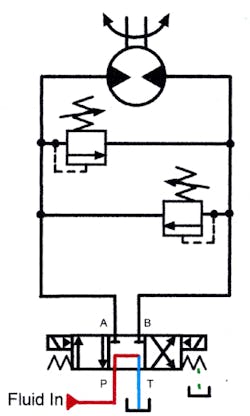
Figure 12-18 depicts the most common way to slow a hydraulic motor with an over-running load. Notice that the directional valve has blocked ports A and B. This valve’s center condition makes a motor stop abruptly, which could cause high shock and physical damage. Shock occurs because the motor becomes a fixed-displacement pump without a relief valve to protect it from over pressure. The cross-port relief valve shown in the Figure allows fluid from the over-pressured port to go to the opposite motor port. The reason for piping the outlet of the reliefs to the opposite motor port is to keep it from cavitating as the motor decelerates. Cross-port reliefs are available with both relief valves in a common housing to save piping time and reduce potential leakage points.
Set the pressure for the cross-port relief valve the same or higher than system pressure. This gives full starting torque and smooth controlled stopping. When the cross-port relief valve pressure setting is lower than system pressure, it reduces starting and maximum running torque. The only reason for a lower setting at the cross-port reliefs is for longer coasting time. The higher the pressure setting of the cross-port reliefs, the more quickly the motor stops.
By deenergizing the directional valve with the motor at full speed, outlet flow from the motor is blocked and pressure increases. When pressure reaches the setting of the cross-port relief valve, the valve opens and allows flow to the opposite motor port. Backpressure equal to or greater than what it took to start the motor now holds back against the load. The energy of the over-running load dissipates over a short period of time to eliminate shock.
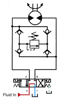
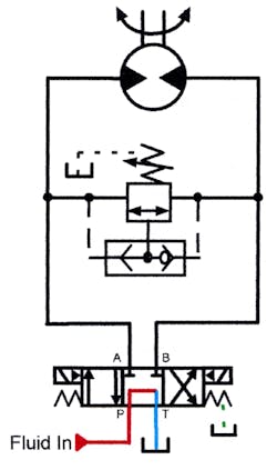
Dual cross-port relief valves allow different stopping times for the two directions of rotation. If this feature is not required, use the single relief and check valves shown in Figure 12-19. With this circuit, pressure is set only once for both directions of rotation. Notice that the check valves direct flow through the relief from either motor port to the opposite motor port. This check valve arrangement is available in a manifold to save piping time.
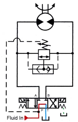
Figure 12-20 shows an externally piloted and drained pressure control valve that slows the motor in both directions. A shuttle valve feeds the pilot port from either motor port to open the pressure control valve. The external drain line allows internal leakage to return to tank. As Figure 12-20 indicates, the pressure control must be set equal to or higher than the system pressure. For longer stopping times, use the piping arrangement in Figure 12-21.
In Figure 12-21, the drain line from the pressure-control valve is piped to the pump line of the directional valve. With the drain line piped this way, the setting of the pressure control is unimportant when the motor is running. Working pressure at the drain port of the pressure control valve adds to the set pressure. Shifting the directional valve keeps the cross-port relief valve from opening when the motor is running.
When the directional valve shifts to its center position, pump flow dumps to tank and the drain line pressure drops, allowing the cross-port relief to operate. This provides pressure lower than system pressure at the cross-port relief valve, so the over-running load takes longer to stop.
Brake valves to control hydraulic motors with over-running loads
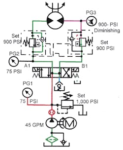
Figure 12-22 depicts brake valves (sometimes called over-center valves) piped in the lines between the motor and the directional valve. To control the motor in both directions of rotation, install two brake valves as shown.
A brake valve is an internally and externally pilot-operated pressure-control valve. The internal pilot works on a small area and thus requires a high pilot pressure. The external pilot works on a larger area at a much lower pilot pressure. A common ratio for pilot areas is 8:1. With an 8:1 pilot-area difference, the valve allows fluid to pass when the internal pilot pressure is 1000 psi or the external pilot pressure is 125 psi. Always note the internal pilot pressure setting on the schematic diagram. The internal pilot setting indicates the amount of backpressure at the motor during deceleration.
Brake valve pressure setting is independent of system pressure. This means a lower or higher pressure on the brake valve does not affect the system’s maximum operating pressure.
Brake valves are necessary when a hydraulic motor’s load tries to make it go faster than the pump or control circuit feeds it. In a winch application, a directional valve shifts to lower a load. Without a brake valve, the winch load falls freely, the motor cavitates, and the circuit is unsafe. Most winch applications require only one brake valve.
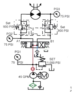
Figure 12-22 shows a brake-valve circuit at rest. The brake valves stay closed because their pressure settings are high enough to stop the load. Notice the internal pilot lines on each brake valve that sense pressure in the motor outlet lines. Also, each brake valve has an external pilot line from the opposite motor flow line. Bypass check valves in each brake valve allow free-flow return during reverse flow.
NOTE: Never depend on any valves to stop and hold a hydraulic motor. Hydraulic motors always have internal leakage and will continue to turn slowly without some external braking arrangement. Spring-on, pilot-to-release, multiple-disk brakes are one method of holding a hydraulic motor stationary.
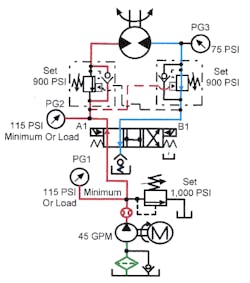
Figure 12-23 shows the brake-valve circuit after shifting the directional valve. Oil entering the left motor port must be at least 112 psi (1/8 of the 900-psi setting) to open the right brake valve. When the load is over-running, inlet pressure to the motor stays at 112 psi to hold the outlet brake valve open. When pressure at the inlet drops below 112 psi, the opposite brake valve closes to retard motor movement. During this portion of the cycle, backpressure keeps the motor from running away. When pressure tries to go above 112 psi, the opposite brake valve opens wide -- dropping all backpressure. As the motor is turning under power, the external pilot supply controls the brake valve.
When the directional valve centers, as depicted in Figure 12-24, external pilot supply to the brake valve drops. The brake valve tries to close, causing pressure to increase at the motor outlet port. When outlet pressure reaches 900 psi, it forces the brake valve open and holds back against the over-running load. Because 900 psi is more than enough to stop the load, the motor decelerates to a smooth controlled stop.
The brake valve only holds the motor back if it is trying to run away. This means little or no energy loss as the motor turns under load — and no running away when the load tries to turn the motor. This action is identical to that of a counterbalance circuit for a cylinder.
Because each brake valve is independent, a different pressure setting at each valve is possible.
Controlling the speed of hydraulic motors
When flow controls set the speed of a hydraulic motor, the result is nearly the same as with a cylinder. The main difference is that cylinders normally have positive seals while motors always have internal leakage. With meter-in and bleed-off circuits, internal leakage causes motor speed to fluctuation as pressure varies.
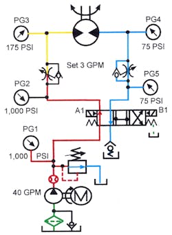
Figure 12-25 shows a motor circuit with meter-in flow controls. This is the preferred way to control the speed of hydraulic motors. Use a meter-in circuit whenever possible because the motor's internal leakage passes to the low-pressure port through internal check valves. This type circuit makes a case drain or high-pressure shaft seal unnecessary. There is little or no backpressure at the outlet of the motor to cause high pressure at the shaft seal.
When supplied with 3 gpm at 100 psi, the motor turns at low torque. Its speed is approximately 200 rpm. When the motor load increases and pressure drop across it climbs, increased internal leakage causes speed to slow by as much as 10 to 30%. (The lower the efficiency of the motor, the greater the change in speed.) Motors that turn very slowly may even stop as pressure drop increases. Fast-turning motors may lose speed but continue rotating. As discussed in the section on flow controls, a pressure-compensated valve keeps a constant flow to the motor but cannot offset its internal leakage.
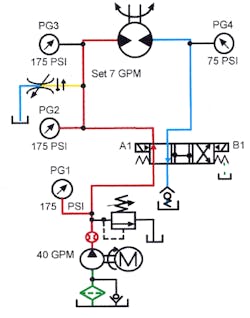
The bleed-off circuit shown in Figure 12-26 is even less effective than the meter-in circuit. With bleed-off flow control, the motor inefficiency combines with the pump inefficiency to produce an even greater loss of rotational speed as the motor loads. The circuit shows a pressure-compensated flow control bypassing 7 gpm. The motor operates at 3 gpm and 100 psi. As the motor loads and pressure increases, internal leakage in the motor and pump results in a greater drop in speed than with the meter-in circuit.
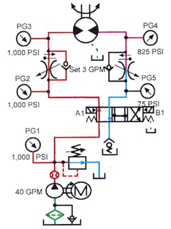
The meter-out circuit shown in Figure 12-27 provides the most accurate speed control. Note that heat generation is high, even with a pressure-compensated pump, but the resulting speed control is very accurate. Use pressure-compensated flow controls and motors with external case drains for the greatest accuracy and longest motor life. Oil enters the motor at low torque and the pressure drop across it is low. Even though high inlet pressure with high backpressure causes high internal leakage, pump input makes up for it. Accurately controlled fluid leaving the motor keeps speed constant because the pressure-compensated flow control maintains a steady flow. When the motor loads, pressure drop across it decreases. Internal leakage decreases but the amount of oil leaving the outlet port stays constant. As long as outlet flow does not change, speed stays the same.
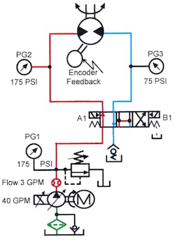
The circuit in Figure 12-28 generates only minimum heat, but speed fluctuates with load changes when using a variable-displacement pump. The only energy loss is from the inefficiency of the pump, valve, and motor. As the load increases, pressure at the motor inlet climbs. The increased pressure causes greater slip at the pump and motor, so motor speed slows. As shown in the Figure, a servo-controlled pump with electronic feedback from the hydraulic motor eliminates the speed change problem and gives extremely accurate speed control.
Simple torque limiter for air motors
Some circuits reduce the inlet pressure to limit air motor torque on a device. Reducing inlet pressure causes the motor to stall when the workload exceeds its torque. Limiting torque with this method is not reliable or repeatable. Torque levels vary by as much as 10 to 20% according to how fast the motor turns, the mass involved, and the pressure required. The faster the motor turns and the heavier the part being turned, the more the torque overrides. Adjusting inlet pressure reduces motor torque but will not overcome the variations that weight and speed cause. Also, adjusting inlet pressure to a very low level makes motor performance erratic, with an ever-changing torque. Finally, at lower pressures, reduced speed may increase cycle time.
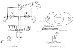
To overcome these problems, try the diagrammed circuit and simplified mechanical layout shown in Figure 12-29. With this circuit, the motor operates at full torque, while meter-in flow controls set its maximum speed. An adjustable spring force holds the motor in position by opposing its torque reaction. As the motor turns to tighten a device, torque is low until near the end of the operation. During this part of the cycle, the adjustable spring resists motor torque, keeping its housing stationary. When motor torque increases to match the amount set by the spring tension, the housing starts to rotate. When torque reaches spring setting, the motor housing moves the reaction arm against the limit switch, shifting the directional valve to center and stopping the motor. This mechanism — designed with minimal friction or binding — gives reliable and repeatable results. Air limit valves or electric limit switches work equally well with this arrangement. Use air limits with snap action shifting for good repeatability.
Hydraulic motor driven by a bi-directional pump
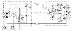
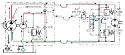
Figure 12-30 shows a variable-displacement bi-directional pump driving a bi-directional hydraulic motor in a closed-loop system. This circuit is commonly known as a hydrostatic transmission. The bi-directional hydraulic pump can produce up to full flow from either port, eliminating the need for directional or flow control valves. When the pump strokes to produce flow from one port, the motor starts turning a given direction. With controlled pump stroking, the motor starts and accelerates smoothly. The amount of pump stroke controls motor rpm and pressure is just enough to make the motor turn. With high-efficiency components, this system generates little heat, eliminating the need for large reservoirs while it gives infinitely variable speed and torque.
Due to internal leakage of the pump and motor, the circuit is not a true closed loop. Without leakage makeup, the circuit would quickly run dry, operate intermittently, and damage its parts. To keep the closed loop full, fixed-displacement charge pump A supplies flow through check valves C1 and C2 to the low-pressure side of the circuit. Charge oil keeps the pump inlet fully supplied, preventing cavitation. When the motor stops, excess oil from the charge pump goes to tank through relief valve B. Oil from the charge pump often operates the pump stroking mechanism, plus other circuits on the machine.
In Figure 12-31, the motor is running forward. Flow from the pump goes to the motor inlet, making it turn. Flow from the motor outlet returns to the opposite side of the pump. Check valve C1 stays closed (due to the working pressure) while check valve C2 opens to allow charge oil to make up for leakage and supply the closed-loop with cooled clean fluid. Shuttle valve E shifts when the motor runs, porting excess charge fluid through relief valve D, the motor case, the pump case, and back to tank. Charge flow sends spent oil through the motor and pump case to cool them, then through a heat exchanger to remove excess heat. Flow goes through relief valve D because its setting is 100 psi less than relief valve B.
While the motor runs, speed is infinitely variable and system pressure fluctuates with any load changes. The only heat generation in this circuit comes from the charge pump going across the relief valve, plus inefficiencies in the pump, motor, and valves.
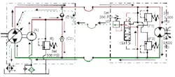
When the motor meets a load large enough to stall it, relief valve F1 opens as shown in Figure 12-32. This directs pump flow around the stalled motor, protecting the system from overpressure. If relief valve F1 stays open for any length of time, the wasted energy quickly over-heats the closed-loop piping.
Relief valves F1 and F2 also protect the motor when the pump goes to zero stroke and an external force continues to drive the motor. When an external force drives a motor, the motor becomes a pump. Pressure at its outlet climbs until it reaches 5000 psi. At 5000 psi, one of the relief valves opens, allowing oil to flow to the opposite motor port. This protects the motor and circuit from excess pressure and possible cavitation. While the externally driven motor bypasses, relief valve backpressure decelerates it, stopping the load quickly and smoothly.
Closed-loop motor circuits give infinitely variable control of torque and speed with minimal shock and heat generation.
