Understanding Proportional Control Valve Circuits
*Editor's Note: This article was updated in April 2024.
The spool in a standard 2-position-solenoid-operated valve shifts all the way to its new position at high speed. (Hence the nickname: bang-bang solenoid.) This rapid, full shift can cause an actuator to jump or lunge on start up and produce excessive shock when stopping. Pressure spikes and shock are noisy, may cause machine damage, and can adversely affect piping, causing leaks.
A soft-shift solenoid with hydraulically dampened spool movement slows the rate of shift and reduces shock in some applications. However, many machines need a variable shifting rate to match changing power and work requirements. Soft-shift solenoids with variable flow controls offer more range and give better control for some circuits.
Other options include valves with specially designed flow controls and spool-stroke adjusters set for a specific machine function. This type of variable valve works on some machines, but requires many precision adjustments to attain the wanted actuator control.
Variable-volume, bi-directional pumps in closed-loop circuits give very smooth action, but are limited to operating a single actuator. For extremely accurate control, a servo valve with actuator feedback is the ultimate motion controller. In between a servo circuit and the other controls mentioned above are proportional valves.
READ MORE: What's the Difference Between a Servo Valve and a Proportional Valve?
How Do Proportional Valves Work?
Proportional valves are well suited for circuits that need to vary either flow or pressure to reduce lunge and shock. The solenoids on these valves shift the spool more or less according to the voltage applied to proportional solenoids. They can change the speed at which the spool shifts or the distance that it travels. Because the spool in a proportional valve does not shift all the way, all at once, the valves can control the acceleration and deceleration of an actuator.
Usually, varying shifting time of the spool controls acceleration and deceleration. Varying voltage to the coil limits spool travel to control the maximum speed of an actuator. A computer, a PC, a programmable logic controller (PLC), or even a simple rheostat can produce the variable electric signal.
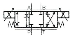
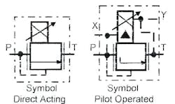
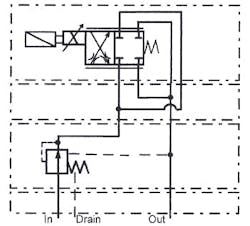
If flow is low (less than 20-25 gpm), use a direct solenoid-operated proportional valve, such as shown in Figure 14-1. Direct-operated valves are smaller and less expensive than solenoid-pilot valves. However, solenoid-pilot proportional valves can handle higher flows — some in excess of 200 gpm.
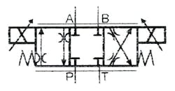
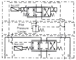
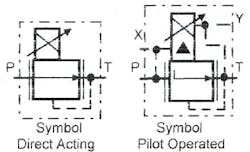
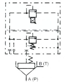
Figure 14-2 shows the simplified symbol for a solenoid pilot-operated proportional valve. Figure 14-3 shows the complete symbol for the same valve. The complete symbol includes details of the control and slave valves, the reducing valve in the pilot circuit, and the routing of the pilot lines.
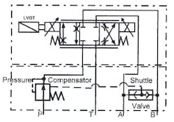
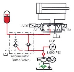
A simple proportional valve depends on solenoid force working against a spring to position the spool. Because flow, pressure, temperature, and fluid cleanliness change constantly, a given input voltage may not always produce the same spool position. To resolve spool position accuracy, use a linear variable differential transformer (LVDT), such as shown in Figures 14-2 through 14-5.
An LVDT electronically compares the input signal with spool position and modifies voltage to give the same spool position regardless of system changes. An LVDT adds cost to the valve and the electronics, but is usually necessary in all but simple acceleration/deceleration circuits.
An LVDT does not control repeatability of flow through the valve because flow is a function of pressure drop and fluid viscosity as well as orifice size. Changes in pressure or fluid thickness will modify actuator speed. To reduce speed change, add a feedback signal from the actuator (similar to a servo valve circuit). Actuator feedback will help but is still not extremely accurate because most proportional control valves do not respond quickly enough to overcome sudden system changes.
In Figure 14-5, the pressure-compensating valve in the inlet line reduces flow fluctuations due to system pressure changes. The pressure compensator maintains a constant pressure drop across the spool orifice to keep flow constant when inlet or working pressures change. The pressure compensator is a reducing valve that has a fixed spring setting (say 150 psi). A shuttle valve provides pressure feedback from each cylinder port to the reducing valve’s remote-control port. As pressure in a working port changes, it modifies reducing-valve pressure to maintain a constant 150-psi drop across the proportional valve’s spool.
READ MORE: A Guide to Flow Control Valve Types and Use Cases
Proper Circuit Design Determines Proportional Valve Control Capabilities
Sending electrical signals to a proportional solenoid to vary the force against a poppet or orifice allows infinitely variable control of pressure. Figures 14-6 and 14-7 show symbols for infinitely variable pressure-relief and reducing valves. Use a PC or PLC to produce the variable signal to change pressure any time the machine sequence requires it.
Remote control of a pressure-compensated pump with a proportional pressure valve makes these pumps more versatile also.
Figure 14-8 depicts the symbol for a slip-in cartridge relief valve. When flows go above 150 to 200 gpm, use a slip-in cartridge relief valve with a direct-acting proportional relief pilot. These cartridge valves come in stand-alone bodies or as part of a special high-flow manifold.
Proportional directional control valves are more tolerant of contamination and cost less than the servovalves that they often replace. When a circuit does not require extreme accuracy or flow repeatability, the savings in first cost, plus a less-expensive filtration requirement, make proportional valves a good choice.
One reason a servo system is more accurate is the electronic feedback signal from the actuator. The feedback signal modifies the servo valve’s spool position to put the actuator in an exact place, or produce the speed or force that the controller requires. A proportional valve may have feedback control, but the response time of the valve is too slow to get the precise control that a servo valve circuit provides.
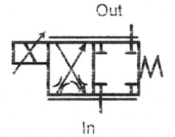
Figure 14-9 depicts a proportional valve used for a throttle function. This valve is an infinitely variable, electrically controlled flow control. As coil voltage increases, the spool shifts farther to increase flow. The symbol in Figure 14-9 shows the valve piped for a single flow path.
Dual flow paths shown in Figure 14-10 give twice the flow at the same pressure drop in either flow path. Use the throttle valve shown in Figure 14-10 to control flow in a bleed-off or bypass circuit, or to control flow to or from a conventional solenoid valve.
The throttle function varies flow to an actuator that needs frequent or constant adjustment. Also use a throttle valve and a conventional directional valve to give smooth acceleration and deceleration of a cylinder to eliminate shock.
A throttle valve in the tank line of a conventional solenoid valve controls actuator speed in a meter-out configuration. The actuator cannot run away with a throttle valve at this location. Make sure the directional valve can withstand any backpressure in the tank line that is greater than the circuit produces.
One throttle valve in the main pump line can vary the speed to one actuator or several that cycle at different times. This type of circuit is less expensive but requires a more-complex electrical control circuit.
The throttle valve configuration in Figure 14-10 gives infinitely variable flow. Adding the hydro stat module to the pump line keeps the pressure drop across the orifices constant. With a constant pressure drop, flow does not fluctuate. Because the 4-way valve never sees reverse flow, both flow paths can supply the circuit. Either flow path has a nominal pressure drop at a specified flow. This arrangement gives twice rated flow without excess pressure drop or heat.
The parallel flow path module comes with all flow paths internally drilled and sized to keep pressure drop to a minimum. This module is available in D03 and D05 sizes for flows up to approximately 50 gpm.
Use proportional control valves to reduce shock and give a finer degree of control to circuits that do not require extreme position accuracy, or repeatable speed and force.
Proportional valves restrict flow to and from an actuator. They work best with a pressure-compensated pump in a closed-center circuit. An accumulator in the circuit enhances cycle response time and protects the pump from pressure spikes. Systems that use proportional valves usually require a heat exchanger because energy waste is higher with this type circuit.
The following sections describe a few more circuits — with some pointers for using proportional valves in several applications. Always remember to size the valves for maximum flow and pressure drop to get optimum response and repeatability from the circuit.
READ MORE: Advanced Electropneumatic Positioning Achieves Dynamic Force Control
Circuit Designs for Proportional Throttle Valves
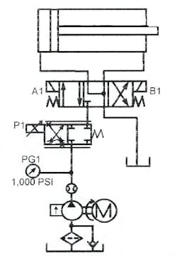
The circuits in Figures 14-11 and 14-12 control acceleration and deceleration of an actuator. Electronic signals to these circuits also can vary the speed of the actuators infinitely.
A proportional throttle valve in the pump line of Figure 14-11 controls flow to a standard solenoid valve. This circuit is good for resistive loads only because it meters fluid to the cylinder. To reduce energy waste, use a load-sensing pump and sense the line between the proportional valve and the directional valve. Load sensing lets the system operate at lower pressures during most of the cycle. Load sensing also makes the circuit pressure compensated.
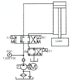
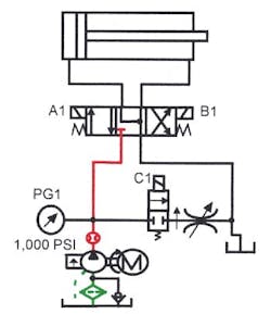
The proportional throttle valve in Figure 14-12 meters flow out of the tank line of a standard solenoid valve. This circuit is good for over-running loads because it meters fluid from the cylinder.
CAUTION: The directional valve may see pressure as high as twice the pump compensator setting. Make sure this pressure does not exceed its tank line rating. Allowing the throttle valve to shift abruptly in this meter-out circuit could result in detrimental shock. Use a proportional control card with adjustable ramps for this application.
If the cylinder must set without creep, use a counterbalance valve. A throttle valve has internal leakage and may not be able to prevent cylinder drift. A counterbalance valve in this circuit must have an external drain. Backpressure at the counterbalance valve outlet modifies the pressure setting of an internally drained valve. (See Chapter 5 for a full explanation of counterbalance circuits.)
A Typical Conventional Valve Circuit for Resistive-Load Applications
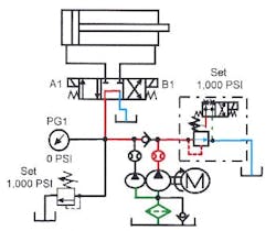
A horizontally mounted cylinder typically requires force at all times to stroke. This cylinder configuration is known as a resistive-load application. Heavy loads at fast operating speeds usually require a means of acceleration and deceleration for smooth operation. One way to control acceleration in these circuits is to shift a standard open-center solenoid valve to extend the cylinder and let excess pump flow relieve to tank during acceleration. A small pressure spike and some heat generation take place during this part of the cycle, but otherwise cylinder start up is smooth.
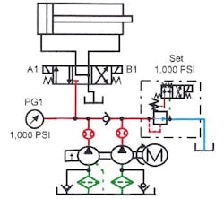
The schematic diagram in Figure 14-13 shows a double pump in a hi-lo circuit that operates this way. Figure 14-14 shows the circuit with a closed-center valve and a pressure-compensated pump. This arrangement eliminates some of the pressure spikes and reduces heat generation, but is more expensive.
When the cylinder approaches the end of its stroke, a limit switch unloads the high-volume pump of the hi-lo circuit, decelerating the cylinder as quickly as friction on the machine members allows. When the cylinder slows to the speed of the low-volume pump, it continues to the end of stroke at a velocity low enough to eliminate most of the shock. (In this application, a cylinder with standard cushions will eliminate virtually all shock.)
Figure 14-15 shows another shock-free deceleration circuit. Here a pressure-compensated bleed-off flow control dumps excess flow from a single fixed-volume or pressure-compensated pump. Deceleration is still as fast as the friction of the machine dictates. Secondary speed is adjustable to meet any requirement.
Another option for decelerating a load is to specify a cylinder with longer than standard cushions that have a tapered flow cutoff. Always specify load, pressure, and speed when ordering tapered cushions. Tapered cushions are very effective for machines that have fixed working parameters. If the load constantly changes, tapered cushions are only effective over a narrow range of the change.
Proportional Valves in Resistive-Load Circuits
The circuit in Figure 14-16 arranges a proportional valve and a pressure-compensated pump to cover all the situations in the previous section. Acceleration and deceleration are fully adjustable through a broad range with this circuit. When the load, speed, or pressure changes, it is easy to change the control parameters to match the new situation. Normally an electronic dashpot changes shifting speed of the spool between zero and five seconds. To make up for changes in fluid viscosity, pressure, or load, decelerate to a minimum creep speed and finally close the valve completely via the end-of-stroke limit switch.
Proportional Valves for Running-Away Loads
Loaded cylinders that are vertically mounted usually run away or over-run pump flow in one direction. When an on/off directional valve shifts, the cylinder free falls. Free fall is a safety hazard that can cause tool or machine damage.
The counterbalance valve in Figure 14-17 controls an over-running cylinder. The valve allows flow from the run-away end of the cylinder as fast as the pump supplies the opposite end. When the cylinder strokes in the opposite direction, the load is resistive. Control acceleration and deceleration with any of the resistive-load circuits in the previous section when using a counterbalance valve.
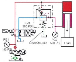
Proportional directional valves control inlet and outlet flow so that there is pressure at both ends of an actuator when it moves. A counterbalance valve often needs an external drain when used with a proportional directional valve. Without an external drain, pressure at the outlet of the counterbalance valve adds to the spring setting that keeps the valve from opening. Notice that the circuit in Figure 14-18 shows the external drain line on the counterbalance valve. With this circuit the cylinder stops smoothly when the proportional directional valve centers rapidly, as in an emergency stop.
Proportional directional valves control running-away loads because most spool designs control flow to and from the actuator. If the actuator is a hydraulic motor or a double rod-end cylinder, volume at the inlet and outlet is the same. As the proportional valve shifts to move the actuator, restricted flow from the opposite side controls acceleration, deceleration, and maximum speed.
However, the majority of cylinders have a single rod, making the volume leaving the rod end less than what enters the cap end. The volume difference is almost 50% when using a 2:1 rod cylinder. In these cylinders, the rod area equals half the piston area. (Some manufacturers offer proportional valves with spools that only allow approximately half flow through the rod port. These valves work well with a 2:1 rod cylinder.)
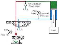
Two problems can occur when using a standard spool-type proportional valve with single-rod-end cylinders and running-away loads. Figure 14-19 shows the cylinder running away from the pump, causing cavitation in the cylinder’s cap end. The cylinder runs away because the proportional directional valve’s meter-out function lets out more oil than it allows in at the cap end. Because the cap end does not stay full, it will pause when it meets a load while the pump fills the cap-end void. When a cylinder runs ahead of the pump, use an anti-cavitation check valve to allow fluid from the tank into the cylinder’s cap end. This circuit works for applications with the over-running load at the cylinder’s rod end.
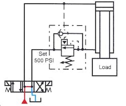
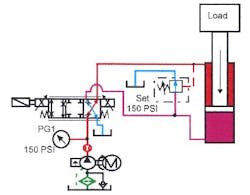
With an over-running load at the cap end of the cylinder, the pump tries to force the cylinder to move faster than fluid can leave it. The excess fluid retards the cylinder’s motion. The circuit works, but the pump wastes energy because it is at full pressure unnecessarily. The circuit in Figure 14-20 shows an external pilot-operated pressure control valve teed into the cap-end line to provide a path for excess fluid to flow directly to tank. Giving the extra oil a second path reduces rod-end pressure and wasted energy. In effect, this is a meter-in circuit for a running-away load.
